The high-end economy lines GSN & GFE combine high performance with financial efficiency: both lines are also equipped with helical ground gears, ensuring the very least noise level and smooth running. The entire needle bearing offers been especially designed to reach high torques that beat the competition for units of the same size. All planetary carriers are manufactured as a cage made from solid materials. This increases silent operating characteristics while at the same time improving positioning precision and reducing backlash. Yet another shaft sealing band ensures maximum dust and splash water protection relative to protection course IP65 in every lines.
One way to reduce backlash is to use precision gears. The concentrate on production in precision gears is usually tighter tolerances, so all over the gear will be a tighter, more specific suit. And the tighter fit means less play in the gear teeth, which is the trigger of backlash in the first place. Of course, precision gears are more expensive, if the application calls for high accuracy, then precision gearing may be the way to go.
From a gear design perspective, a simple way to reduce backlash is to ensure the teeth mesh tightly together. That is typically completed by shortening the center distance between gears. As for pre-loading, this could be done using a spring mechanism to hold the gears firmly set up. This also eliminates the enjoy between the gear teeth and therefore eliminates backlash.
Of course, the type of gears used can also have a huge impact on the quantity of backlash. So for example, some equipment types such as strain wave gears, or harmonic gear drives, have zero backlash.
The GSD, GSB & GSBL high-end gearbox lines are constructed in a space-optimized, two-stage design. Because of the lower torque ideals, the input stage is dimensionally smaller than the result stage. Its short design makes the GSD series the perfect high-end gearbox for space restricted applications. The low standard backlash of the GSD series makes it an ideal fit for highly powerful applications where highest positioning and quickness accuracy is required. The flange output produces highest torsional rigidity. For the lodging of especially high axial loads, taper roller bearings are elective in sizes with 90 mm diameter or more. The GSB line means high performance in combination with low backlash and high precision. Its robust, one-piece housing allows for a higher gearbox rigidity and the absorption of high radial and axial loads. The angular gearboxes of the GSBL line offer the same advantages as the GSB collection; the right angle form makes the GSBL series an ideal match for all powerful applications where space is limited.
Incorrect tolerances, bearing misalignment, and manufacturing inconsistencies tend to increase backlash.
AC motors and gear motors include single-stage motors used with a single-stage AC power and three-stage motors used in combination with a three-stage AC power. A single-phase motor could be operated by simply linking it to a single-phase power supply via the provided capacitor. A three-phase motor will not require a capacitor. All you have to is for connecting the motor right to a three-phase AC power supply.
The brand new planetary gearbox series includes the high-end gearbox lines GSD (flange gear), GSB (inline) and GSBL (angle gear) as  well as the high-end economy GSN and GFE lines. Particularly ideal applications for the brand new range are those which place the best demands on positioning precision, operating noises, running worm drive servo smoothness, bending rigidity and transmitted torque. The planetary gears are designed to meet the highest creation requirements – all lines include precision floor helical gearing, single-piece planetary carriers and complete needle bearings.
 gearboxes
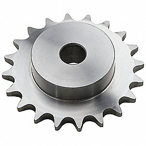 STYLES
 motor specifically designed for 50 rpm. A gearhead’s ratio reduces the engine rpm, which explains why gearheads are sometimes called gear reducers. Using a gearhead with a 40:1 ratio,
 air movements further toward the center of the spirals, the surroundings pockets become smaller, and the surroundings in those pockets gets compressed.
 divided into a traveling sprocket and a driven sprocket. The generating sprocket is installed on the engine output shaft by a spline; the driven sprocket is certainly mounted on the motorcycle generating wheel, and the power is definitely transmitted to the driving wheel through the chain. The drive sprocket is usually smaller than the driven sprocket, which can reduce the speed and raise the twist.