Product Description
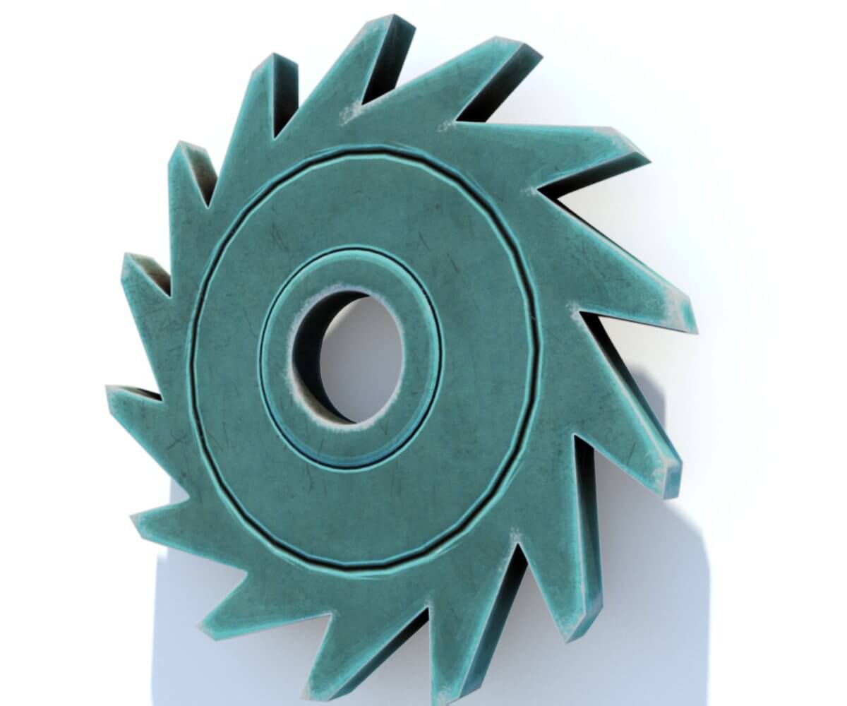
Introducing the Carrier Pin Wheel for Ratchet Pin Wheel by HangZhou Xihu (West Lake) Dis.an Hardware Technology Co., Ltd. This unique pin wheel is made of alloy steel and is perfect for customized processing and packaging machines. It features five-axis machining and CNC machining components for precision and durability. Upgrade your machine with this high-quality pin wheel today!
Product Description
| Production type |
Custom production and processing |
Material |
Metal, non-metal, carbon steel, stainless steel, copper, aluminum alloy |
| Processing methods |
CNC Trining Parts 5-axis CNC machining centers, grinding machines, wire cutting |
Processing Equipment |
CNC Trining Parts 5-axis CNC machining center, grinder, wire cutting |
| Accuracy |
±0.05mm |
Whether proofing |
yes |
| Is it customized |
yes |
Proofing time |
7-15 days |
| OEM/ODM |
OEM ODM CNC machining service |
surface treatment |
Electroplating, zinc plating, chrome plating, nickel plating, oxidation, hard oxidation |
| Origin |
HangZhou, China |
Quotations |
FOB |
| Business Type: |
Manufacturer/Factory & Trading Company |
Main Products: |
CNC parts; Machining parts |
| Management System Certification: |
ISO 9001:2015 |
Average Lead Time: |
Peak Season Lead Time: within 15 workdays Off Season Lead Time: within 15 workdays |
Product Parameters
Discover our high-quality Cam Machining Parts for Semiconductor Vibration Plate. Made from alloy steel, these precision components are perfect for the semiconductor industry. With our advanced machining technology, we provide reliable and custom CNC parts for your needs.
Calm and Soothing Product Description: Cam Machining Parts for Semiconductor Vibration Plate
Introducing the Cam Machining Parts for Semiconductor Vibration Plate, brought to you by HangZhou Xihu (West Lake) Dis.an Hardware Technology Co., Ltd. Our high-quality machining parts are designed to enhance the performance of your semiconductor vibration plate, providing you with reliable and efficient solutions for your semiconductor manufacturing needs.
Our precision cam components are meticulously crafted using advanced machining technology. The alloy steel construction ensures durability and longevity, making these parts a reliable choice for your cam wheel assembly. With our custom CNC parts, you can expect precise and accurate machining, guaranteeing optimal performance.
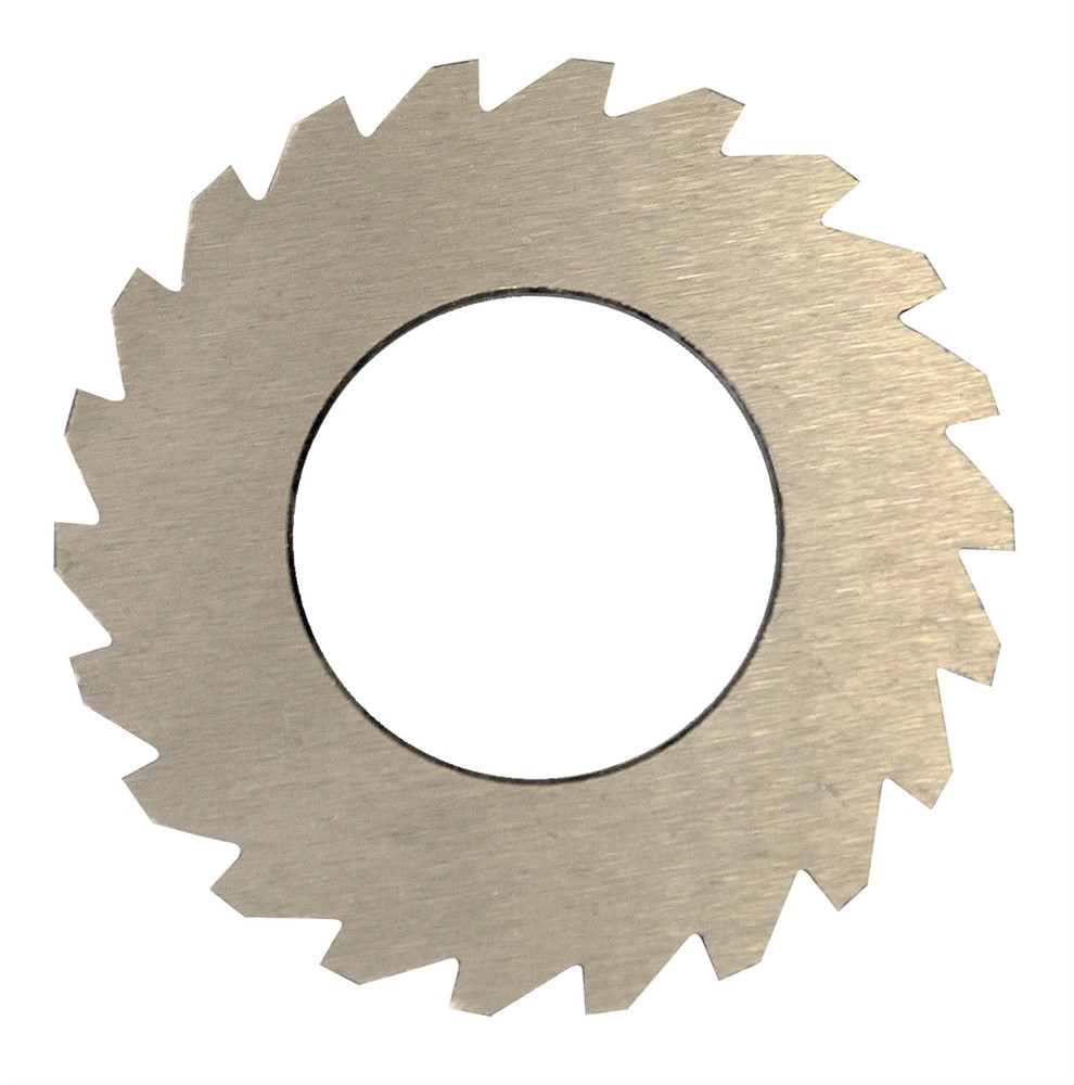
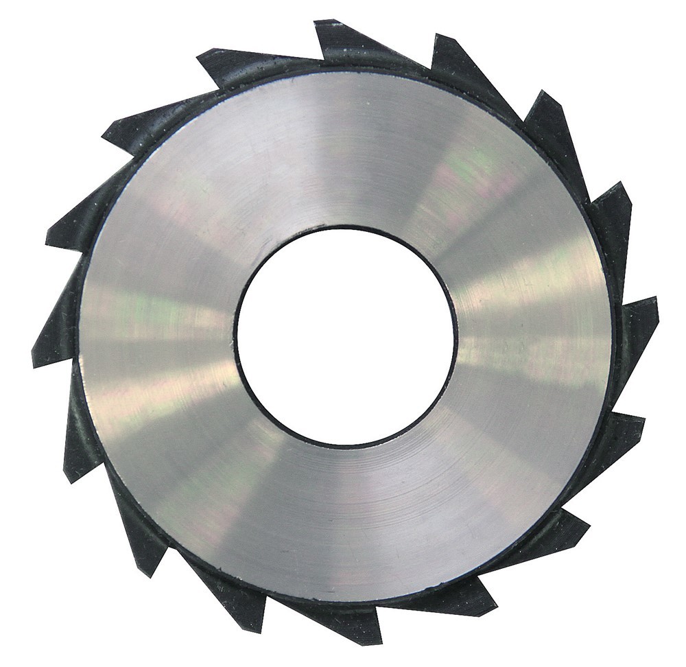
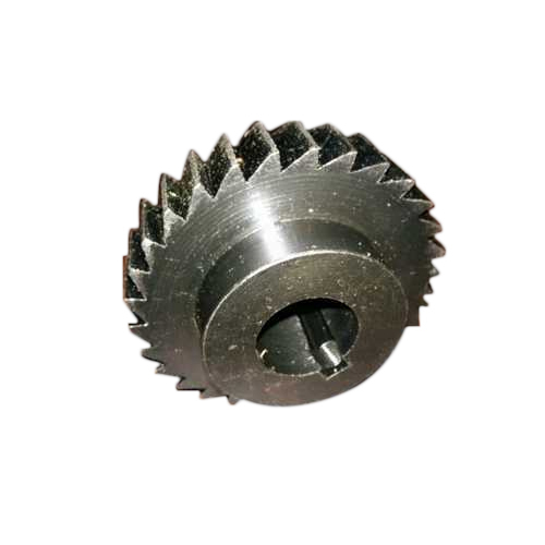
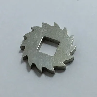
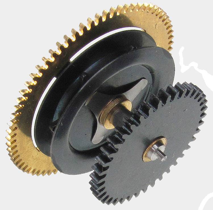
At HangZhou Xihu (West Lake) Dis.an Hardware Technology Co., Ltd., we understand the importance of precision in the semiconductor industry. That’s why our cam machining accessories, such as the pulling wheel, carrier pin wheel, and ratchet, are manufactured with utmost care and attention to detail. These components play a crucial role in the smooth operation of your vibration plate, ensuring consistent and reliable performance.
With our expertise in precision machining, we offer machining services that meet the highest standards. Our CNC parts are processed using CNC turning and precision 5-axis CNC, resulting in a rough blank that is then surface electroplated for a flawless finish. This meticulous process guarantees the quality and reliability of our machining parts.
Choose HangZhou Xihu (West Lake) Dis.an Hardware Technology Co., Ltd. as your trusted machining supplier for all your semiconductor vibration plate needs. Experience the benefits of our high-quality cam machining solutions and take your semiconductor manufacturing to the next level.
Calm and Soothing Product Description: Motor Shaft Copper Sleeve
Introducing the Motor Shaft Copper Sleeve, a high-quality precision component designed to enhance the performance of your machinery. Crafted with utmost care and expertise by HangZhou Xihu (West Lake) Dis.an Hardware Technology Co., Ltd., a reliable machining supplier in the semiconductor industry.
Our Motor Shaft Copper Sleeve is made from H59 brass, a material known for its exceptional durability and reliability. Through precision CNC turning and 5-axis CNC milling, we ensure the utmost accuracy and precision in every detail of this component.
To further enhance its longevity and aesthetics, the Motor Shaft Copper Sleeve undergoes a meticulous electroplating process for surface treatment. This not only adds a touch of elegance but also provides an extra layer of protection against wear and tear.
With its impeccable craftsmanship and advanced machining technology, our Motor Shaft Copper Sleeve is the perfect choice for semiconductor vibration plates, cam machining parts, pulling wheels, carrier pin wheels, ratchets, and more. Its compatibility with various machinery makes it a versatile solution for your machining needs.
Experience the difference of our Motor Shaft Copper Sleeve and elevate the performance of your machinery. Trust in the expertise of HangZhou Xihu (West Lake) Dis.an Hardware Technology Co., Ltd. to deliver high-quality machining parts that meet your exact specifications.
Robot accessory bracket: Made of AL6061 aluminum alloy through 5-axis milling and natural surface treatment.
Calm and Soothing Fine-Tuning Dial for Terminal Machines and Mechanical Equipment
Introducing our high-quality fine-tuning dial, designed to bring precision and durability to your terminal machines and mechanical equipment. Made from carbon steel with exceptional hardness, this dial has undergone meticulous processing using CNC lathe and precision 5-axis CNC technology. To ensure longevity, the surface has been electroplated for added protection.
At HangZhou Xihu (West Lake) Dis.an Hardware Technology Co., Ltd., we specialize in providing top-notch machining parts for various industries. Our Cam Machining Parts for Semiconductor Vibration Plate are meticulously crafted to meet the demanding requirements of the semiconductor industry.
Key Features:
- Alloy steel construction for enhanced strength and reliability
- Precision machining using advanced 5-axis CNC technology
- Customizable CNC parts to suit your specific needs
- Perfect for semiconductor manufacturing and vibration plate components
-
-
With our fine-tuning dial, you can easily adjust the scale of your terminal machines and mechanical equipment, ensuring optimal performance and efficiency. Whether you need to fine-tune a pulling wheel, carrier pin wheel, or ratchet, our dial is the perfect solution.
Trust in our reliable machining services and benefit from our expertise in the semiconductor industry. Our Cam Machining Parts are designed to deliver exceptional performance and longevity, making them the ideal choice for your machining needs.
Calm and Soothing Speech Microphone
Experience the tranquility of our Speech Microphone, crafted with precision using AL6063 aluminum alloy material. Through the meticulous process of CNC lathe and 5-axis CNC, this microphone is transformed into a masterpiece. Its surface is delicately oxidized with a luxurious gold finish, adding a touch of elegance to any setting.
Designed for various public places, our Speech Microphone is perfect for KTV, schools, karaoke halls, stages, and speeches. Its exceptional quality ensures crystal-clear sound transmission, allowing your voice to resonate effortlessly. Whether you’re addressing a crowd or performing on stage, our microphone guarantees a calm and soothing experience for both you and your audience.
Trust in the expertise of HangZhou Xihu (West Lake) Dis.an Hardware Technology Co., Ltd., a reliable machining supplier in the semiconductor industry. Our Cam Machining Parts for Semiconductor Vibration Plate are meticulously crafted using advanced machining technology. With precision cam components and high-quality machining parts, our solutions cater to the specific needs of the semiconductor manufacturing process.
Key Features:
- Alloy steel construction for durability and longevity
- Five-axis machining for precise performance
- Custom CNC parts tailored to your requirements
- Reliable and efficient machining services
-
-
Enhance your semiconductor vibration plate with our Cam Machining Parts. From pulling wheels to carrier pin wheels and ratchets, our machining accessories are designed to optimize the performance of your equipment. Experience the seamless integration of our steel ratchet wheel and precision cam components, ensuring smooth operation and increased productivity.
Choose HangZhou Xihu (West Lake) Dis.an Hardware Technology Co., Ltd. for all your machining needs in the semiconductor industry. Our commitment to delivering high-quality machining parts and exceptional customer service sets us apart. Trust in our expertise and let us provide you with reliable solutions that exceed your expectations.
Titanium Alloy Interface
Experience the exceptional quality and precision of our Titanium Alloy Interface. Crafted from Tc4 titanium alloy material using state-of-the-art CNC processing techniques, this interface is perfect for a wide range of applications including equipment interfaces, mechanical interfaces, and aviation plug interfaces.
Company Profile
About Us
Welcome to HangZhou Xihu (West Lake) Dis.an Hardware Technology Co., Ltd., a renowned manufacturer with over 20 years of industry and trade expertise. Located in HangZhou City, ZheJiang Province, China, we pride ourselves on our advanced high-end professional production and processing technology. Our dedicated team of technical management personnel, experienced designers, and R&D experts work tirelessly to deliver innovative solutions. With a perfect company management system in place, we are committed to providing you with the highest quality products.
CNC Training Parts
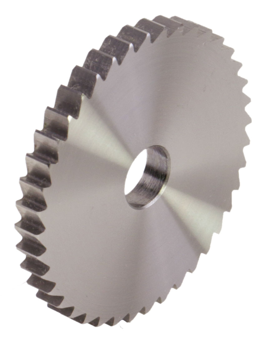
Introducing our Cam Machining Parts for Semiconductor Vibration Plate, designed to meet the specific needs of the semiconductor industry. Made from alloy steel and manufactured using advanced five-axis CNC machining technology, these precision parts include pulling wheels, carrier pin wheels, ratchets, and more. Our high-quality machining solutions ensure reliable performance and seamless integration into your semiconductor manufacturing process.
5-axis CNC Workshop
Discover high-quality machining parts and custom CNC solutions for the semiconductor industry. Our advanced machining technology and reliable supplier services ensure precision and efficiency. Explore our range of cam machining parts, including semiconductor vibration plates, pulling wheels, carrier pin wheels, ratchets, and more. Trust in our expertise in alloy steel machining and precision cam components. Choose HangZhou Xihu (West Lake) Dis.an Hardware Technology Co., Ltd. for all your machining needs.
Calm and Soothing Product Description: Cam Machining Parts for Semiconductor Vibration Plate
Introducing our high-quality Cam Machining Parts for Semiconductor Vibration Plate, designed and manufactured by HangZhou Xihu (West Lake) Dis.an Hardware Technology Co., Ltd. With a focus on precision and reliability, our machining parts are perfect for the semiconductor industry.
Our factory, spHangZhou over 2,000 square meters, is equipped with state-of-the-art production equipment, including CNC lathes, 5-axis CNC, 4-axis CNC, stamping equipment, and die-casting equipment. This allows us to master core processing technologies and deliver exceptional results.
Featuring alloy steel construction, our Cam Machining Parts are built to withstand the demands of the semiconductor manufacturing process. The precision machining ensures optimal performance, while the cam wheel assembly guarantees smooth and efficient operation.
With our advanced machining technology, we offer custom CNC parts tailored to your specific requirements. Whether you need pulling wheels, carrier pin wheels, ratchets, brooch pins, or any other cam machining accessories, we have you covered.
Choose our Cam Machining Parts for Semiconductor Vibration Plate and experience the benefits of reliable machining. Trust in our expertise and let us provide you with high-quality machining solutions for your semiconductor industry needs.
Three-dimensional Imager
Enhance your production process with our high-quality auxiliary production equipment. Our range includes electroplating, anodizing, hard anodizing, and surface treatment equipment. These advanced technologies ensure superior results and impeccable surface finishes.
At HangZhou Xihu (West Lake) Dis.an Hardware Technology Co., Ltd., we prioritize precision and quality. That’s why we offer a complete range of testing equipment to ensure the utmost accuracy in our products. Our sophisticated three-dimensional testing, two-dimensional testing, hardness tester, height meter, projector, and other conventional testing equipment guarantee the highest standards of quality control.
If you are interested in our products, please don’t hesitate to contact us. We are committed to providing the best price support and quality service to meet your needs.
Welcome to HangZhou Xihu (West Lake) Dis.an Hardware Technology Co., Ltd., where we specialize in providing high-quality machining parts for the semiconductor industry. Our expertise lies in producing precision cam components, including cam machining parts, pulling wheels, carrier pin wheels, ratchets, and more.
Our Advantages
We take pride in our long-standing partnerships with reputable material suppliers, ensuring that the materials we use are of the highest quality. Whether you require aluminum alloy, steel alloy, carbon steel, stainless steel, copper, brass, titanium alloy, bronze, nylon, or acrylic, we have you covered. Rest assured that all our materials come with supporting documents for your peace of mind.
When it comes to surface treatment, our experienced suppliers are well-versed in meeting the stringent quality requirements. From heat treatment to spray painting, powder coating to plating, we offer a wide range of options to suit your specific needs. Our surface treatment processes include aluminum alloy surface oxidation, ensuring a durable and visually appealing finish.
At HangZhou Xihu (West Lake) Dis.an Hardware Technology Co., Ltd., we understand the importance of precision and reliability in the semiconductor industry. That’s why we utilize advanced machining technology and employ a five-axis machining approach to deliver exceptional results. Our CNC parts are custom-made to meet your exact specifications, guaranteeing a perfect fit and optimal performance.
Choose us as your reliable machining supplier, and experience the benefits of our high-quality machining parts. Whether you need components for vibration plates or cam machining accessories, we have the solutions you’re looking for. Trust in our expertise in the semiconductor manufacturing industry, and let us provide you with top-notch machining services.
Discover the difference that our alloy steel machining can make in your operations. Our precision cam components and steel ratchet wheels are designed to withstand the demands of the semiconductor industry, ensuring long-lasting performance and reliability.
Contact us today to discuss your requirements. We welcome your pictures and letters, and we look CHINAMFG to establishing a good and long-term cooperation with you. Thank you for considering HangZhou Xihu (West Lake) Dis.an Hardware Technology Co., Ltd. as your trusted partner in precision machining.
HangZhou Xihu (West Lake) Dis.an Hardware Technology Co., Ltd. offers high-quality dust-free electroless nickel plating on carbon steel surfaces. Perfect for semiconductor vibration plates, our precision machining parts, including cam machining accessories and steel ratchet wheels, are the ideal solution for the semiconductor industry. Trust our reliable machining services and advanced technology for all your machining needs.
FAQ
Product Description: Cam Machining Parts for Semiconductor Vibration Plate
Our Cam Machining Parts for Semiconductor Vibration Plate are precision-engineered components designed to enhance the performance and reliability of semiconductor vibration plates. Made from high-quality alloy steel, these parts are meticulously machined using advanced CNC technology and five-axis machining techniques.
With our expertise in the semiconductor industry, we understand the critical role that vibration plates play in ensuring smooth and efficient operations. Our Cam Machining Parts, including pulling wheels, carrier pin wheels, ratchets, and brooch pins, are specifically designed to meet the demanding requirements of the semiconductor manufacturing process.
By utilizing our custom CNC parts, you can optimize the performance of your vibration plates, resulting in improved productivity and reduced downtime. The precision cam components and steel ratchet wheels ensure smooth and precise movements, allowing for accurate positioning and reliable operation.
At HangZhou Xihu (West Lake) Dis.an Hardware Technology Co., Ltd., we take pride in our commitment to delivering high-quality machining parts. Our experienced engineers and skilled workforce, along with our state-of-the-art workshop, ensure that every component meets the highest standards of quality and precision.
When you choose our Cam Machining Parts, you can expect exceptional craftsmanship, reliable performance, and long-lasting durability. We prioritize customer satisfaction and strive to exceed your expectations with our reliable machining solutions.
Whether you need machining services for semiconductor vibration plate components or any other precision machining requirements, we are your trusted supplier. Rest assured that your product drawings and specifications will be kept confidential, and we will provide regular updates on the production progress, including detailed schedules, digital pictures, and videos.
Experience the difference of working with a reliable machining supplier. Contact HangZhou Xihu (West Lake) Dis.an Hardware Technology Co., Ltd. today to discuss your specific needs and discover how our Cam Machining Parts can enhance the performance of your semiconductor vibration plates.
Packaging & Shipping
Calm and Soothing Tone: Cam Machining Parts for Semiconductor Vibration Plate
Experience the highest quality machining parts with our Cam Machining Parts for Semiconductor Vibration Plate. Designed and manufactured by HangZhou Xihu (West Lake) Dis.an Hardware Technology Co., Ltd., a reliable machining supplier in the semiconductor industry, these precision cam components are perfect for your semiconductor manufacturing needs.
Our Cam Machining Parts are made from alloy steel, ensuring durability and long-lasting performance. With advanced machining technology and five-axis machining capabilities, we guarantee precise and accurate results every time.
Featuring a ratchet wheel, pulling wheel, carrier pin wheel, and brooch pin, our Cam Machining Parts provide exceptional functionality and reliability. They are designed to optimize the performance of your vibration plate, ensuring smooth and efficient operation.
Whether you need custom CNC parts or cam machining solutions, our machining services have got you covered. We offer a wide range of packaging options to suit your requirements, including commercial packaging and industrial packaging.
Trust HangZhou Xihu (West Lake) Dis.an Hardware Technology Co., Ltd. for all your machining needs. Contact us today to learn more about our Cam Machining Parts for Semiconductor Vibration Plate and how they can enhance your semiconductor manufacturing process.
/* March 10, 2571 17:59:20 */!function(){function s(e,r){var a,o={};try{e&&e.split(“,”).forEach(function(e,t){e&&(a=e.match(/(.*?):(.*)$/))&&1
| After-sales Service: |
Professional Service |
| Warranty: |
30 Days |
| Certification: |
ISO9001, ISO, CE |
| Samples: |
US$ 100/Piece
1 Piece(Min.Order)
|
Order Sample
|
.shipping-cost-tm .tm-status-off{background: none;padding:0;color: #1470cc}
Shipping Cost:
Estimated freight per unit.
|
about shipping cost and estimated delivery time.
|
| Payment Method:
|
|
|
|
Initial Payment
Full Payment
|
| Return&refunds:
|
You can apply for a refund up to 30 days after receipt of the products.
|
What maintenance practices are recommended for ratchet wheels to ensure optimal functionality?
Maintaining ratchet wheels is essential to ensure their optimal functionality and longevity in mechanical systems. Here are recommended maintenance practices for ratchet wheels:
- 1. Regular Inspection: Perform routine visual inspections of the ratchet wheel and the surrounding components. Look for signs of wear, damage, or deformation. Pay attention to the teeth, as worn or damaged teeth can affect engagement.
- 2. Cleaning: Keep the ratchet wheel and associated components clean from dirt, debris, and contaminants. Clean with a suitable solvent or degreaser to remove built-up grime and ensure smooth operation.
- 3. Lubrication: Apply a suitable lubricant to the ratchet wheel and pawl or catch mechanism to reduce friction and prevent premature wear. Follow the manufacturer’s recommendations for lubrication intervals and types of lubricants.
- 4. Pawl or Catch Inspection: Check the pawl or catch mechanism that engages with the ratchet wheel. Ensure it is in good condition, and there is no excessive wear or damage. Replace worn or damaged pawls promptly.
- 5. Alignment: Verify that the ratchet wheel is correctly aligned with the pawl or catch. Misalignment can lead to uneven wear and reduced effectiveness. Make any necessary adjustments to ensure proper engagement.
- 6. Tightening Fasteners: Periodically check and tighten any fasteners, such as bolts and nuts, that secure the ratchet wheel and its associated components. Loose fasteners can lead to play and affect performance.
- 7. Teeth Replacement: If teeth on the ratchet wheel show signs of significant wear or damage, consider replacing the ratchet wheel or the affected teeth. Damaged teeth can lead to unreliable engagement.
- 8. Corrosion Prevention: In corrosive environments, take measures to prevent rust or corrosion on the ratchet wheel. This may include applying protective coatings or using corrosion-resistant materials.
- 9. Calibration (If Applicable): In applications requiring precise control, consider calibrating the ratchet wheel to ensure it provides the desired incremental movement accurately.
- 10. Safety Check: Ensure that ratchet wheels in safety-critical applications are functioning correctly and have not been compromised in any way. This includes systems in vehicles, safety equipment, and emergency mechanisms.
- 11. Replacement: As ratchet wheels age and show significant wear, it’s advisable to replace them to maintain the reliability and safety of the system.
Regular maintenance and inspection of ratchet wheels are essential to prevent unexpected failures, ensure proper engagement, and extend their service life. Following these maintenance practices helps maintain the optimal functionality and reliability of ratchet wheels in mechanical systems.
Can you provide insights into the importance of proper installation and alignment of ratchet wheels?
The proper installation and alignment of ratchet wheels are of utmost importance for ensuring their functionality, longevity, and safety in mechanical systems. Here are key insights into why proper installation and alignment matter:
- 1. Precision and Efficiency: Correct installation and alignment ensure that the ratchet wheel engages smoothly with the pawl or catch mechanism. Proper alignment minimizes friction and maximizes the efficiency of controlled motion, allowing for precise and repeatable adjustments.
- 2. Preventing Premature Wear: Misaligned or improperly installed ratchet wheels can experience uneven wear on their teeth. This can lead to premature wear and decreased service life. Proper alignment distributes loads evenly, reducing the risk of wear and damage.
- 3. Safety Considerations: In safety-critical applications, such as emergency stop systems, the alignment of ratchet wheels is vital. Misalignment can compromise the safety of these systems, leading to unintended operation or failure to engage when needed. Proper alignment ensures reliable safety mechanisms.
- 4. Avoiding Slippage: Correct alignment ensures that the pawl or catch securely engages with the ratchet wheel’s teeth. Improper alignment can result in slippage, where the wheel fails to hold its position or lock as intended. This can be hazardous in applications requiring stability and security.
- 5. Reducing Maintenance Costs: Misaligned ratchet wheels are more likely to require frequent maintenance and replacement. Properly aligned ratchet wheels experience less wear and stress, leading to longer service intervals and reduced maintenance costs over time.
- 6. Enhancing Durability: Well-aligned ratchet wheels are more durable and can withstand higher loads and forces. This durability is essential in applications where the ratchet wheel is subjected to heavy use or challenging conditions.
- 7. Consistency in Operations: Properly installed and aligned ratchet wheels contribute to consistent and repeatable operations. Whether in manufacturing, assembly, or other tasks, consistency is critical for achieving desired outcomes and quality standards.
- 8. Minimizing Vibration and Noise: Misalignment can lead to unwanted vibrations and noise in mechanical systems. Proper alignment reduces these disturbances, contributing to a quieter and smoother operation.
- 9. Compliance with Specifications: Many industries have specific standards and regulations governing the installation and alignment of critical components like ratchet wheels. Proper alignment ensures compliance with these standards and ensures that the system operates as intended.
In summary, proper installation and alignment of ratchet wheels are essential for precision, efficiency, safety, and overall system performance. Investing time and care in the initial installation process pays off in terms of reliability, reduced maintenance, and improved safety in mechanical systems.
Can you explain the primary purpose and applications of ratchet wheels in various industries?
Ratchet wheels serve a primary purpose in various industries by enabling unidirectional motion, preventing backward movement, and offering precise control. Their applications are diverse and include the following:
- 1. Automotive Industry: Ratchet wheels are integral to automotive applications, such as handbrakes and vehicle jacks. Handbrakes use ratchet mechanisms to securely hold a vehicle in place, preventing it from rolling when parked on an incline. Vehicle jacks employ ratchet mechanisms for controlled lifting and lowering of vehicles during maintenance or tire changes.
- 2. Construction and Engineering: Construction and engineering equipment often feature ratchet mechanisms. Ratchet straps and tie-downs are used for securing loads on trucks and trailers. Additionally, ratchet wrenches and torque wrenches provide precise control in construction and assembly tasks, allowing for incremental tightening or loosening of bolts and fasteners.
- 3. Manufacturing and Assembly: Ratchet mechanisms are employed in manufacturing and assembly processes where controlled movement is essential. This includes machinery used in factories for precision tasks like fastening, clamping, or incrementally advancing components on an assembly line.
- 4. Medical Devices: The medical industry utilizes ratchet wheels in various instruments and devices. For instance, surgical instruments may feature ratchet mechanisms to control the movement of specific components, allowing surgeons to perform delicate procedures with precision.
- 5. Material Handling: In material handling equipment such as winches, hoists, and cranes, ratchet wheels ensure the controlled lifting and lowering of heavy loads. They contribute to safety and prevent unintended load movement, making them crucial in industries like construction, manufacturing, and logistics.
- 6. Consumer Products: Ratchet mechanisms are found in many consumer products. A common example is a retractable tape measure, where a ratchet wheel allows the tape to be extended and then locked in place at the desired length. Similarly, many hand tools like screwdrivers and pliers feature ratchet mechanisms for efficient and continuous rotation in one direction.
- 7. Aerospace and Aviation: Ratchet wheels are used in aerospace and aviation applications for tasks like securing cargo in aircraft, controlling movements in cockpit instruments, and ensuring the proper operation of various components within the aircraft.
- 8. Marine and Boating: Marine equipment often employs ratchet mechanisms in winches and pulleys for controlling sails, anchors, and other rigging. They enable sailors to adjust sail tension and anchor position with precision.
- 9. Sports and Recreation: Ratchet mechanisms are used in sports and recreational equipment, such as bike gears and fishing reels. They provide controlled motion and prevent backward movement, enhancing the user experience and safety.
Ratchet wheels are versatile components that find applications in an array of industries, improving safety, control, and efficiency across various mechanical systems.


editor by CX 2024-01-16
 many projects that included varied sizes of custom made worm gears to print requirements.
 can get this product at marketplace leading prices.
 gadgets and safety switches
 extremely strong and light-weight. They are are .100” thick and accept regular .25” (1/4”) metallic or plastic chain.
 high-grade electricity transm
 id-Couplings.jpg]#ission technologies, braking and cooling methods, and hydraulic factors.
 a more substantial pitch diameter than before with this adjustment. Meet every need in your market by slowing the machinery right down to a specific rate. Simply raise the space between your two discs, which decreases the belt’s motion. At EVER-POWER, our adjustable pulleys give you the necessary adaptability to refine your machinery and move forward with a productive day.
 why.
why. Name:
Name: the timing belt used to operate a vehicle the camshafts within an car or motorcycle engine.
 the laboratory or anywhere a low vacuum is needed; typically give both vacuum and pressure features. Use tough vacuum pumps (or roughing pumps) for laboratory and industrial applications requiring an even of vacuum less than 10-3 Torr. Use high vacuum pressure pumps when you need vacuums greater than 10-3 Torr. Also, consider the free-air capacity needed (the bigger the free air capacity, the faster it will evacuate the chamber) and whether you need a lubricated (oiled) or non-lubricated (dried out or oilless) pump. Lubricated pumps offer higher capacities, higher vacuum amounts, and lower sound, but can contaminate the machine and require more maintenance.
  of the standard tests.
 to increase backlash.
  move back and forth once, it is readily apparent that the input swiftness will determine the amount of strokes or urgings the clutches supply the output shaft each and every minute.
 faster but doesn’t change the sound from the engine as much as a conventional two rate or one rate. This confuses some riders and qualified prospects to a mistaken impression of too little power.
 the right is a specialty customized manufactured
  Our spiral bevel gearboxes could be given up to four shafts, hollow shaft and with an output torque as high as 1,000 Nm and will end up being fitted with a engine flange with a good coupling for direct mounting of the motor.
 gear drives are often accessible in the function assistance is ever required.
 to reduce speed and/or transmit higher torque while changing path 90 degrees. Worm gearing is a sliding actions where the work pinion pushes or pulls the worm gear into action. That sliding friction creates heat and lowers the effectiveness ranking. Worm gears can be used in high-torque situations in comparison to other options. They certainly are a common option in conveyor systems since the equipment, or toothed wheel, cannot move the worm. This enables the gearbox motor to continue operation regarding torque overload and also emergency stopping regarding a failure in the system. It also enables worm gearing to handle torque overloads.
 they could just travel in
  save money and time when identifying and purchasing gears. These pitch templates can be purchased in nine sets to recognize all the normal pitch sizes: Diametral Pitch “DP”, Circular Pitch “CP”, External Involute Splines, Metric Module “MOD”, Stub Tooth, Great Pitches, Coarse Pitches and Uncommon Pitches. Make reference to the section on GEAR GAGES for catalog numbers when ordering.
 software, water pump, floor polisher, pickup truck lift, salt spreader, stair lift, hospital bed
 low-torque; the addition of a worm drive increases the range of applications that it might be suitable for, especially when the worm drive’s compactness is known as.
 effective answer for power transmitting applications requiring high-ratio swiftness reduction in a restricted space using correct angle (90°), non-intersecting shafts. When properly used, worms and worm gears provide the smoothest, quietest form of gearing.
 good spur gear in which the tooth are machined on the internal circumference of an annular wheel, these mesh with the exterior teeth of a small pinion. Both tires revolve in the same course. Internal gears have a much better load carrying capability than an external spur equipment. They are safer used because the teeth will be guarded. They are generally applied to bicycle gear changing pumps, system and planetary gear reducers.
 than the central
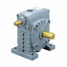 of a solid or hollow result shaft and show an adjustable mounting placement. Both the SW-1 and the SW-5, nevertheless, can endure shock loading much better than other reduction gearbox styles, making them well suited for demanding applications.
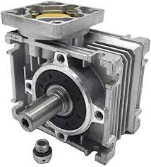 tranny of higher horsepower amounts than are possible with standard cast iron products. Extra heavy aspect plates connect the worm and equipment shaft bearing supports, assuring proper meshing of the gear under all load conditions. In smaller sizes, fabricated steel reducers are interchangeable with Ever-Power standard cast iron reducers.
 the torque output will reduce. Gear drive selection elements include: shaft orientation, rate ratio, design type, nature of load, gear ranking, environment, mounting position, working temperature spectrum, and lubrication.
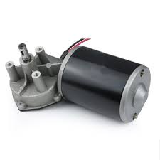 more than a few seconds at a time.
 so a position can be kept even when power is not applied. The precision ground 3/8” stainless steel output shaft is supported by dual 3/8” ABEC 5 ball bearings to support lots from any orientation. The ¼” ABS plastic and aluminum structure offers a rigid framework without adding unnecessary fat and is very easily mounted to any flat surface by utilizing the base mounting tabs. Our Regular Spur Gear motors will continue to work with this gearbox (electric motor marketed separately). The Vertical Shaft Worm-Drive Gearbox is ideal for turn-tables, time-lapse systems and low-acceleration applications that want high precision and torque.
  the emphasis is on space effectiveness.
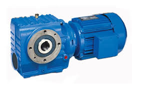 and helical worm gearboxes / geared motors (S and SS)
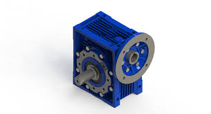 gear reducers, quickness reducers, equipment drives, and gearmotors. All terms can be used more or less interchangeably. Please be aware that the inbound links for our little gear drives include details on the full range of framework sizes for that series or design.
 specific match. And the tighter fit means much less play in the gear teeth, which is the trigger of backlash to begin with. Of training course, precision gears are more expensive, but if the application demands high accuracy, after that precision gearing could be the way to go.
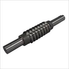 repeatedly engages the worm gear, the materials of the worm has to be considerably harder than that of the wheel. Because of this, worms are typically produced from metal and worm wheels are typically created from bronze alloys. It’s quite common to harden and grind worms specifically when they are going to be used under excessive load or working at substantial speeds such as inside a reduction drive gearbox.
 standard for food machinery.
 quickness reducers are mechanical swiftness reduction equipment used in automation control systems.
 they are a type of bevel gear, bevel gears have some basic features, such as spur gears, helical gears, and zero-tooth equipment types.
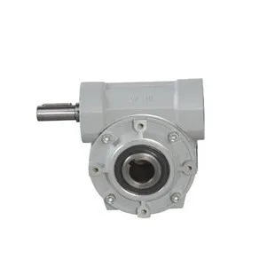 Input & Output Shafts for Worm Gearboxes
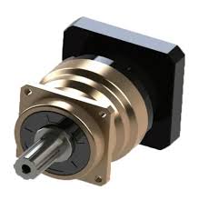 email us. The application info will be reviewed by our engineers, who will recommend the best solution for your application.
 angle bevel gearbox combines the top features of our correct angle worm and planetary inline reducers. With a solid and efficient correct angle configuration, our right angle planetary gearboxes offer a robust solution. The proper angle bevel gearbox will come in 18 ratios ranging from 5:1 to 1000:1, in fact it is back-drivable at all ratios.
 helical gears, but its helix angle is typically comparatively larger) and its body is normally quite lengthy in the axial path. The gears in these gearboxes could be right or left-handed depending upon the purpose.
 the gearbox is dependent upon correct selection. The selection of a gear unit is definitely influenced by the course of duty of the crane which should be determined and specified. Single, Dual and Triple stage Horizontal equipment models type HA, HB and HC are suggested for Hoist and Long Travel drive. Three stage vertical gear units type VC are suggested for cross travel drives of the EOT crane. Assembly arrangement must be specified while buying the gear units.
 tail edge of the tooth transmitting power from the input and the leading edge of the immediately following one. The gap is essential for gears to mesh with one another without getting stuck and to offer lubrication within the casing. On the drawback, the mechanical enjoy is associated with significant motion losses, preventing a motor from reaching its optimal performance. To begin with, the losses influence negatively performance and precision.
 and so forth. Furthermore, we can produce personalized variators, geared motors, electrical motors and other hydraulic items according to clients’ drawings.
 technically advanced, high velocity, low backlash servo software planetary gearbox. Our Break through patented technology (over 6 patents), supplies the client with the the best possible high precision helical reducer at a reasonable price and emerges with the only suggestion to toe 5-12 months warranty in the market today, including the seals and bearings. Our company slogan is TRUTHFUL RESPONSIBLE CREATIVE. The primary focus in daily operation is quality. We satisfaction ourselves on our dedication to quality; our duty, is customer satisfaction. We are constantly improving processes, finding appropriate and effective methods to provide customers new solutions for hard applications, and developing services.
  up a hill and around a tree.
 being spread evenly. The spiral bevel gears in a Ever-Power gearbox are precisely adjusted via a unique, adjustable locknut design.
 where nhsg = the number of followers or rollers in the fixed housing and nops = the quantity for followers or rollers in the sluggish velocity output shaft (flange).
 with an assortment of predefined roller and raceway crowns, or with a measured crown.
 reducer.
 Using a gearhead with a servo motor or using an integrated gearmotor can enable the use of a smaller motor, thereby reducing the machine size and price. There are three primary advantages of going with gears, each of which can enable the use of smaller sized motors and drives and therefore lower total system cost:
 In order to center the device before the install, stick to these easy steps:
 complete the installation in six different ways.
 to be the the majority of fuel efficient, as less fuel is wasted during gear alter; in these systems, the operator determines when to change gears and activates the clutch system. Automatic transmissions perform gear changes based on liquid pressure in the gearbox, and the operator provides limited control over the system. Semi-automatic transmissions today see wider use, and invite the user to activate a manual gear alter system when required, while normal gear functions are controlled automatically.
 in relatively brief periods
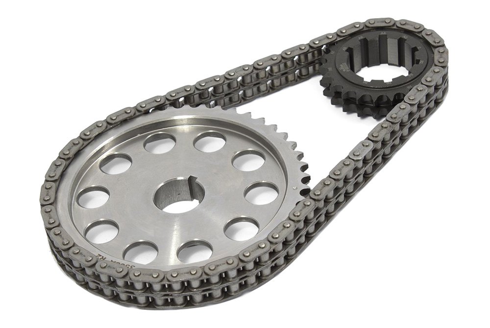 systems can also be tailor-made to offer movements to either direction. This is achieved through integrating two or more motors on either end of the conveyor system.
 moderate loads and speeds, it is extremely easy to restoration and install. Something vital that you note when setting up and using metal detachable chain is that the closed end of the tab should always end up being towards the sprocket. We stock both painted and non-painted SDC chains so when ordering please specify which series you are interested in.
 the sprockets. Silent chains drives are not truly silent. The links in a silent chain drive, however, build relationships the sprocket the teeth with little influence or sliding, and consequently a silent chain creates less vibrations and sound than other chains. The amount of noise generated by a silent chain drive is dependent of many factors including sprocket size, swiftness, lubrication, load, and drive support. A web link belt silent chain includes removable links became a member of by rivets or interlocking tabs. These chains offer the advantage of installation without dismantling drive elements, reducing inventory, and increasing temperature ranges
 Standard Roller Chains. These chains are designed for general usage.
 standards you demand from your tools, such as fighting off debris accumulation and acclimating to nearly every temperature alter. Agricultural roller chain goes through extensive examining and quality checks before it finds your farm. Try our agricultural smooth link chain for easy operations every day. If you want trusted agricultural conveyor chain parts in a hurry.
 excess axial forces total little more than an inconvenience. Gearbox designers will often upsize the bearings to support the additional forces.
 equipment motor has the ability to handle numerous load requirements; the more gear stages (stacks), the bigger the strain distribution and torque transmission.
 (-40°C)
 All fasteners are stainless steel. Hard anodized aluminum or 316 Stainless housings are available. Customizing for other than NEMA motors or your specific application is quickly done.
 and the top speed gear is obtained. When the left dog clutch meshes with the second gear on the main shaft, the next speed gear is achieved. Similarly, by sliding the right-hand dog clutch left and right, the first speed gear and reverse gear are attained respectively In this type of gearbox, because all of the gears are in continuous mesh, they are secure from being damaged and unpleasant grinding audio does not happen while engaging and disengaging them.
 robust and torsion resistant casing so as to ensure long service life standards. The housing is constructed of quality close grained Grey Cast Iron that is proportioned to ensure proper radiation of heat generated when the models are operated at optimum capacity. Further, ideal ribs are placed under bearing seats for high strength with walls of enough thickness to withstand many severe stresses faced during operation. Additional, we also hold expertise in providing housing in cast metal/fabricated steel finish if required.
 and permits precise positioning tasks.
 of electric motor size and type which best satisfies the customer’s requirements and application.
 way of acceleration and deceleration, the instantaneous torque borne by the output shaft of the Planetary reduction drive exceeds 2 times of its rated output torque, and this kind of acceleration and deceleration can be too frequent, which will eventually make Planetary reduction drive break the shaft.
 does not accommodate parallel displacement of shafts but does accommodate angular misalignment. This sort of couplings are primarily utilized for “floating shaft” programs.
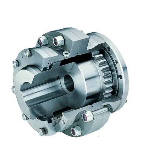 to as a gear-kind versatile, or versatile coupling. The solitary joint allows for minor misalignments this kind of as set up errors and changes in shaft alignment because of to working situations. These kinds of equipment couplings are generally limited to angular misalignments of one/4â1/2°.
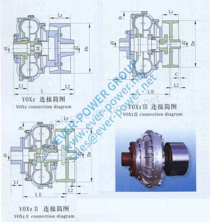 suppliers now.
 ore on it based
  mostly on the fluid in the outer load immediately modify the working cavity quantity, therefore play a function overload defense.
 %20coupling2.jpg]#design
  conveyors, crushers, fanatics, pumps and blowers. They are utilised in numerous industries such as energy technology, steel Era, mining and quarrying, petrochemical and foodstuff producing. They have offered over 70 several several years of dependable successful procedure, and nonetheless give the engineer with a reliable approach of commencing an doing work hefty industrial tools.
 upon request
 or 450 Nm.
 Furthermore, 12 M4 holes in it also allow to be used as the plate in Ever-power platform.
 x 4 x 5 = 60). Inside our example above, the 3,450 rpm electric motor would have its speed reduced to 57.5 rpm by using a 60:1 gearbox. The 10 lb-in electric motor torque would be risen to 600 lb-in (before efficiency losses).
 machines requiring high accuracy positioning.


 almost everything seems normal, attempt changing the gear-mesh. This is carried out with the mylar “gaskets” that sit among the primary gearbox circumstance and the enter/output caps. Consider introducing or taking away some of these spacers until finally your gears have about one/8″-one/four” of free enjoy. Pros can buy replacements ($1-two) in various thicknesses, but we suggest the swift and filthy method of chopping your possess out of a sheet of mylar.
 ISO 606, ready to install
 high input speeds and a little package size with an excellent price/performance ratio.
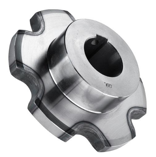 uniform.
 Fabricated using premium quality material, these products adhere to the international quality requirements. Further, we make sure that these Pulleys are made as per the sector norms to make sure their reliable utilization. Our clients can get these casting products in various sizes and dimensions according to their needs.
 and non-standard products available. We are able to produce as per your drawing or sample. Material can be standard or as per your special request. If you choose us, you choose reliable.
 tapered roller bearings are standard for the ISO Flanged Reducers.
 originally suitable for use in small sprockets, now suitable for a great many other lighter-duty applications
 variety of industrial and mobile applications.
 generating torque. Multiple contact factors across the planetary gear teach permits higher torque generation compared to one of our spur gear motors. Subsequently, an EP planetary equipment motor has the capacity to handle different load requirements; the more equipment stages (stacks), the higher the strain distribution and torque transmitting.
 expensive. As an automotive supplier and industrial partner, you can expect solutions that help keep people safer and healthier. We help secure the environment and present individuals more opportunities to shape their own future.
 provides an example and a formulation for dealing with inertia in gearbox selection.
 every Original Equipment Manufacturer worldwide to create products for new automobiles as they are being developed. These solid relationships as well as Ever-power commitment to continuous innovation allow us to provide a complete line of OE quality products for the Aftermarket. From Timing Belts to Micro-V AT Belts, Tensioners and Hose, for both import and domestic vehicles, install with confidence, install Ever-power.
 intrusion.
 motor flanges
 between cords and other sections. This way, heat build-up is reduced, extending belt life.
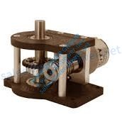 Hypoid versus. Worm Gears: A More AFFORDABLE Right-Angle Reducer
 a simple structure which can be utilized with electrical motors for output rate reduction, huge torque and good capability of enduring overload. This gearbox is an ideal option for working two loads from one motor and extremely serves the objective of operating machinery like conveyors, rotary table, and packaging machinery.
 and so on for several years. Our design concept is as follows.
 are setting up some of the highest quality parts obtainable in the automotive aftermarket – all meeting or exceeding the Original Equipment Manufacturer’s specifications.
 tonnes).
 gears: Provides higher efficiencies and greater torque capacity in smaller sized sizes.
 brinnell marks that are the effect of a frozen slide are at all times evident on leading and back floors of the cross trunnion.
 shaft to become a flying missile, or it may strike and break a thing that is attached or installed on the trunk of the tractor. Separation of the driveline shaft isn’t a commonly occurring celebration but is most probably to happen when three-point
  safety mechanisms that must be in location to protect yourself and your investment. The very first thing you notice when looking at a PTO shaft is the plastic material sleeve that encases the entire length of the shaft between your tractor and the attachment, the metal shaft is actually turning inside of this simple protective casing, avoiding curious onlookers from grabbing a higher horsepower turning shaft and seriously doing some damage to their hands and hands. The next thing you might notice may be the bolts and plates that can be found at one end of the shaft, these bolts and plates are the automatic pressure relief system that manufacturers put on them to release pressure if for example a tiller digs partially into hard floor that it could not power through, one of two
 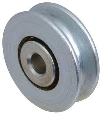 ISP is exclusively available from Ever-power. It offers a simple method of steering flat steel belts. Users may combine ISP steering with the original belt tracking designs of crowning, flanging, and timing elements to make a synergistic belt tracking system which efficiently and exactly steers the belt to specified tracking parameters.
 patrons the very best quality selection of Mechanical Coupling.
 and worm gears provide the smoothest, quietest type of gearing.
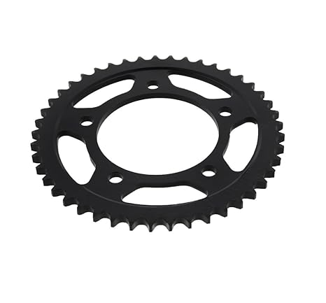 very best chains by each manufacturer so do not inquire about cheaper chains as we don’t want our customers calling back upset and for that reason we only sell what we believe in and know to be the very best. All of our chain kits also come with a rivet master link for the best safely, quality, and performance.
 another piece of metal attached to the axle which can consider this axle torque and transfer it further up the frame, thus relieving the dropout itself from currently taking all of the stresses.
 and supports direction control as well as PWM acceleration control. Rated voltage is 12v and can achieve 16RPM.
 generally used to take a rated motor speed and produce a low speed result with higher torque worth based on the reduction ratio. They often can solve space-saving problems since the worm equipment reducer is one of the sleekest reduction gearboxes available because of the little diameter of its output gear.
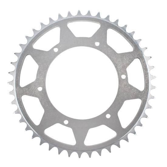 Ever-power aluminium rear sprockets have already been precision CNC machined to an extremely limited tolerance. With a case hardened primary they provide the ultimate combination of minimal weight, optimum strength and hardness.
 which has polypropylene inside links and 304-stainless metal pin links.
  replaced a little early. It’ll be less expensive than waiting until following the belt breaks.
 doubleworm version, with or without the torque limiter, also accumulate, creating a highly versatile drive system.
 worm drive gearboxes. Gear reduction boxes feature a gear arrangement in which a equipment in the type of a screw, also known as a worm, meshes with a worm gear. These gears are usually made from bronze and the worms are steel or stainless steel.
 Strong and long lasting. – Are designed for horizontal and vertical forces concurrently. These bearings are perfect for moderate acceleration, heavy-duty applications where sturdiness is required.
 fact, today, this type of drive mechanisms are those that offer greater efficiency.
 also supply special bushings manufactured from other machinable components. Please inquire
 remember that each host firearm must be examined for baffle alignment via visible inspection before firing.
  locks, you simply press the lock down or to the part to ensure that the door is locked effectively and securely. Nevertheless, with vitality locks, you press option and all doors in the vehicle lock simultaneously. The energy of this is through many of things together with your car battery plus your door lock actuator. A door lock
  to mar the shaft. One piece clamp-on shaft collars simply slide onto the shaft and are guaranteed with a screw. They clamp evenly around the shaft for this reason providing excellent holding vitality. Made of T303 stainless steel which provides excellent corrosion level of resistance. Our shaft collars can be found in several different styles to meet you or your customer’s needs. Climax Steel Products Co. running a business for over 60 years is the leading maker of shaft collars, rigid couplings & keyless locking assemblies. Climax Metals, where fair market pricing and wonderful customer support is our promise for you.
 a (little) savings. While the ceramic ball is approximately one-half the pounds of a metal ball the same size, it’s the stiffness that’s important in their performance.
 cross-section gear rack designs in a
 0.3-0.5mm after precise grinding
 to be engaged at the same time as one’s teeth roll across one another.
 with cast iron bushed bore pulley
 relationships every other tooth. Sprockets will have an extended life as chains engage with different teeth every time the rollers rotate (when actual number of the teeth is odd).
 bearings, pulleys, wheels, etc. Precise combinations vary, based on specific reducer type. What’s common for all combinations-they are intended to transmit power from the electric motor output towards the strain in order to reduce rate and increase torque in a safe and consistent manner.
 well on virtually any shaft. They’re also long lasting, cost-effective and incredibly simple to use: simply slide the collar into position and tighten the screw to lock it in place.
 rapid availability along with optimal reliability and optimum economy within a lifespan of more than 20,000 hours.
 of which usually incorporates a gear. Together with attachment holes in both rings, they enable an optimized power transmitting with a simple and quick interconnection between adjacent machine parts. The bearing raceways, in conjunction with the rolling components and cages or spacers, are designed to accommodate loads performing singly or in combination, and in virtually any direction.
 – tailored precision up to ≤ 2 arcminutes for a number of applications. You profit from rapid availability along with optimal reliability and optimum economy within a lifespan greater than 20,000 hours.
 sale to assembly to practically all servo motors, and the hollow bore result can be utilized to mount output shafts, pinion shafts, or other drive elements.
 power and larger axial load potential than setscrew collars
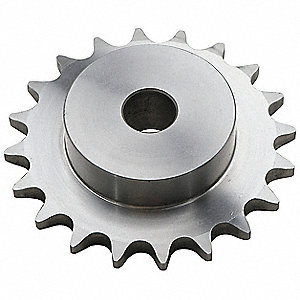 STYLES
 air movements further toward the center of the spirals, the surroundings pockets become smaller, and the surroundings in those pockets gets compressed.
 divided into a traveling sprocket and a driven sprocket. The generating sprocket is installed on the engine output shaft by a spline; the driven sprocket is certainly mounted on the motorcycle generating wheel, and the power is definitely transmitted to the driving wheel through the chain. The drive sprocket is usually smaller than the driven sprocket, which can reduce the speed and raise the twist.
 lubrication. The drive sleeve is usually supported on anti-friction tapered roller or ball thrust bearings. Rotation of the drive sleeve causes the acme thread lifting screw to translate or rotate, depending upon jack configuration.
 a housing. Air will come in through a valve, typically called the inlet valve and can be taken into the space
  excellent choice for applications that require accuracy and reliability. Planetary gearboxes possess very low backlash ratings (typically ranging from one to nine arc-min), so when sized correctly offer a service existence of over 20,000 hours with practically no maintenance. Helical planetary gears provide very calm and more efficient operation in comparison with competitive products.
 rotating to the required position and then rests upon arrival.
 galvanized tubes. Adding these sleeves will make sure that the plastic-type is held in place on the pipe or tube. To essentially get the plastic-type material held securely you can add self tapping screws onto the conduit piping. All your pipes together will continue to work as you entire unit to roll up the plastic-type material on your greenhouse. Ropes can be added anytime to make sure that they plastic-type material or film stays set up when it’s especially windy outside.
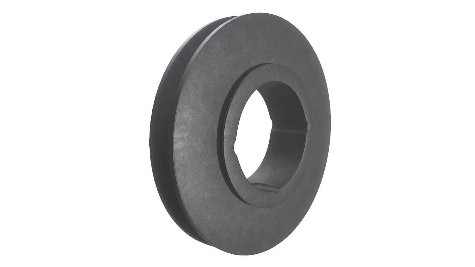 two digits represent the maximum bore size and the second two digits represent the bushing length. For example, product number 1008 has a max bore of just one 1.0″ and a complete amount of 0.8″
 low horsepower or low acceleration. The speed specifications for these motors are regular speed and stall-velocity torque. These motors use gears, typically assembled as a gearbox, to lessen speed, making more torque available. Gearmotors ‘re normally utilized in applications that require a lot of force to go heavy objects.
 cause a squeaking noise at low speeds. Clicking or knocking sounds specifically can signify a faulty CV joint. Any noises such as they are an indicator that the vehicle should be serviced as quickly as possible.
 – 27% faster
  4 times. Middle the steering wheel, and check the liquid level. If the fluid level hasn’t risen and there is no foaming present, the air has been removed. If the power steering pump continues to be noisy, repeat the cycling treatment. If the problem returns after a day time or two, carefully examine the pressure hose. A deteriorated pressure hose makes it possible for air flow to enter the system. Replace the pressure hose. Examine the tire pressure, and lower the vehi-cle. Road test.
 setting up or establishing a final drive, the way the pinion gear contacts the ring gear must be considered. Preferably the tooth get in touch with should happen in the precise centre of the band gears the teeth, at moderate to full load. (The gears force from eachother as load is definitely applied.) Many final drives are of a hypoid design, which implies that the pinion gear sits below the centreline of the ring gear. This enables manufacturers to lower your body of the car (because the drive shaft sits lower) to improve aerodynamics and lower the vehicles center of gravity. Hypoid pinion gear the teeth are curved which causes a sliding actions as the pinion equipment drives the ring equipment. It also causes multiple pinion equipment teeth to communicate with the ring gears teeth making the connection more powerful and quieter. The band equipment drives the differential, which drives the axles or axle shafts which are connected to the rear wheels. (Differential procedure will be described in the differential section of this content) Many final drives house the axle shafts, others make use of CV shafts like a FWD driveline. Since a RWD last drive is exterior from the tranny, it requires its oil for lubrication. This is typically plain equipment essential oil but many hypoid or LSD final drives need a special type of fluid. Refer to the service manual for viscosity and other special requirements.
 one-quit engine source. We carry used and remanufactured engines, for any make and model, international, household and the hard-to-find.
 with dual result shafts. These OP shafts connect to long jack shafts that spread over the roof line of the greenhouse linking to multiple rack and pinion mechanisms that open and close large cup screen panes in the ceiling for temperature control.
 weather control systems are a necessity. Numerous mechanical systems can be used in this respect; however glass vent drive systems have a tendency to be the most popular. we has been providing solutions for this kind of application for twenty years. The drive system includes a central gearmotor connected to a 40:1 right angle reducer with dual result shafts. These OP shafts hook up to long jack shafts that spread across the roof line of the greenhouse connecting to multiple rack and pinion mechanisms that open and close large glass home window panes in the ceiling for temperature control.
 with a ball bearing for installation. These sprockets generally provide stress for the chain drive and can be utilized within a tension arm assembly or separately mounted to position the drive. Share sizes are for sale to ISO 05B thru 20B metric chain sizes. Double-Single Sprockets, well-known on conveyors, allow 2 single chains about the same sprocket to control pairs of rolls or drive models that must index. Custom Metric or ANSI Sprockets Custom made sprockets including large diameter steel or cast iron devices for solitary, duplex or triple strand chain could be made to order. PTI typically helps to keep some stock in our European warehouse, so delivery could possibly be rather quick. Additional customized sprockets sizes for Metric conveyor chain or ANSI chain are also feasible. Drawings are preferred to insure requirements are obvious. Each is possible with customized finished bore.
 steering column. The steering shaft has a pinion attached which attaches to a linear equipment with teeth called the rack. When the tyre is rotated, the gear on the shaft turns onto the rack and enables it to grasp onto the teeth of the rack, which in turn turns the wheels. Tie Rods, which help drive and pull the wheels when turning, are mounted on the Steering Rack at each end. The system is fluid driven by the energy Steering Pump. The Power Steering Pump forces ruthless onto the Steering Hose, which connects to the Rack and distributes fluid to help with lubrication for the shifting components.
 three-phase motor will not need a capacitor. All you have to is for connecting the motor directly to a three-stage AC power supply.
 – what are the limits of temperature desired
 competition.”
 when starting a turn (the rack is near the center), and also reduces effort close to the wheel’s turning limits.
 reduces electrical power costs as expensive lover cooling isn’t needed.
 on the ‘rack’, a amount of metal with some teeth cut involved with it. In order the pinion rotates, the rack movements either left or correct, depending on your steering input.
 inventory which
  a specially selected, high-strength Nylon materials that outwears and outlasts UHMW-PE and polyurethane sprocket alternatives. All sprockets are equipped with standard integral teeth to keep tooth alignment and are designed for use with Polychem collector chain.
 ward off diseases and fungi. In addition being able to change the atmosphere can create excellent air circulation for your plant life in your greenhouse. Any greenhouse can possess roll-up sides added to it, regardless of the type or size. The majority of roll-up sides you obtain will come with all the necessary hardware to be able to effectively build add them on your greenhouse.
 select a manual crank or an incrementally automatic system. Our fabric is a heavy-duty 12 mil. coated 10’x10′ weave fabric (not really 6 mil. poly), solid enough to endure the abuse of windy conditions and also rocks thrown by lawn mowers and weed-eaters. Growers choose curtains that roll up from the middle as opposed to rolling up from underneath; crank rotations are decreased by 50%, and curtains are kept straight. Inexpensive and easy to operate natural ventilation and also adaptable to any greenhouse with straight sidewalls.
 a satisfactory cone grasp and press fit.
 and which is consumed along the way of photosynthesis. Ventilation can be accomplished in a number of ways including end-wall structure exhaust fans combined with inlet louvers, passive peak vents or ridge vents coupled with roll-up sides, roll-up sides alone in an area with reliable crosswind, or even huge doorways on each endwall.
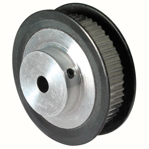 timing pulleys in aluminium or steel versions.
 strip and the PTO coupler to strip.
 edge backand forth to cover and uncover the curtain while the stationary advantage holds thepanel in place.
 is heated is decreased, the quantity of cold air ismaximized. This helps it be harder to mix and reheat the surroundings above the system whenit uncovers each morning. Retrofitting can also be a problem if the gaslines, electrical conduits and heating pipes are mounted at gutter level.
 switch or sensor, you will find all types of switches & sensors and we have a terrific choice of OEM specification replacement spares created to keep you, your tractor and other people safe. Check out the items shown upon this web page for the factor you need. You can also filter the list by tractor help to make and unit. Our catalogues cover over 200 manufacturers and 17,000 tractor configurations.
 pump, pipes and gutters are used to recirculate the drinking water. A flow rate 113 gallon each and every minute per linear foot of pad system should be provided to assure adequate wetting.
 good summertime breezes and plenty of space between houses is needed. It can help to have greenhouses made with a vertical sidewall up to the elevation of the attachment rail to reduce the quantity of rain that can drip in.
 contribute to efficiency, quality and profitability for your greenhouse business. Exhaust enthusiasts also functions great in workshops and buildings.
 it dramatically enhances plant growth.
 easily onto the piston rod and may harm the rubber. Also do not forget to unlock the vent in the winter if leaving the vent openers set up. A good weak winter sun can high temperature the hydraulic cylinder sufficiently to make it start pushing the piston rod outwards.
 a large portable greenhouse today.
 starts to snow.
 and weather that can change in minutes. See how our in-share inventory of chains for everything from combines to forage harvesters helps maintain farms moving throughout the country.
 The agricultural tractor to apply driveline presents a obstacle to the engineer as the universal joint angles vary continuously in three planes and telescope continually in length, which requires a knowledgeable variety of pieces to attain a reasonable uniform transfer of motion. Many agricultural drivelines are suitable for standard tractor pto shaft sizes and speeds. Other drivelines are being used internally in the agricultural implements. The 540 rpm pto shaft, learn shield, and drawbar romantic relationship standard originated by Equipment Companies Institute (EMI) and American World of Agricultural Engineers (ASAE) in 1926. In 1958 a standard for a 1000 rpm tractor pto shaft was published.
 ease and comfort when coupling the PTO, because you may get a good grasp in the limited shaft space.
 implement where inertia of driven unit may be required to over-run generating source. The coupler drives solidly from tractor to apply and free wheels smoothly when apply exceeds tractor PTO speeds. All sizes are nominal.
  dc bus and the voltage on that phase becomes positive. When we close one of the bottom level switches in the converter, that phase is linked to the harmful dc bus and becomes negative. Thus, we can make any phase on the engine become positive or negative at will and can therefore generate any frequency that people want. So, we can make any phase be positive, negative, or zero.
  to stream. When B-stage turns into more positive than A-phase, then the B-phase diode will open up and the A-phase diode will close. The same is true for the 3 diodes on the negative part of the bus. Hence, we obtain six current “pulses” as each diode opens and closes.
 unique power curve, speed overall performance and interface requirements. The tables here are performance
  setpoint with a regulating loop. Adjusting the flow or pressure to the real demand reduces power usage.
 gears simply by pressing a button, turning a knob or toggling a small joystick. Yet simultaneously,
  such as a tractor, at one end and an attachment, for instance a brush hog mower, at the different. When the tractor’s engine is running, power flows along the shaft. The shaft rotates at engine swiftness, transferring strength from the engine to the attachment.
 to easily take away the shaft from the hub for repair or replacement.
 Gearboxes As Per Their Specific Requirements.
 a financial institution of batteries supplying DC current to emergency oil pumps that supply oil to the bearings of a turbine during an emergency shutdown. A second way to obtain DC current could possibly be from a (Motor-Generator) MG established. In cases like this, the electric motor drives a DC generator that generates the DC current. These 1st two types of drives offer pure DC current, for that reason they do not produce any significant electrically induced indicators when it comes to vibration. The last kind of DC drive, and the one which will be talked about in this paper, uses silicon managed rectifiers (SCRs) to rectify AC current into DC Current. These drives produce a DC transmission with AC pulses that correspond to the firing of the SCRs. These pulses or lack thereof regarding failed SCRs and or gating complications produce
  and Spur gears are generally called “Rack and Pinion”. Rack and pinion combinations are often used as part of a simple linear actuator, where in fact the rotation of a shaft powered yourself or by a electric motor is converted to linear motion.
 advantage of the condition of the artwork in electric motors and frequency converters, the driving system for the superimposition of the earth carrier is based on a Permanent Magnet Synchronous Superimposition (SI) engine and an Active Front-End Cycle Converter. So – E stands for Electric.
 versions with load managing capacities from 1/4 ton to 100 tons. They might be used separately or in multiple arrangements. There are no “standard” travel lengths and all
  loads and apply force more efficiently than other machine screw actuators
 thread of screw jack could be acme screw and ball screw. So are there few variants of the screw jack. Commonly, machine screw jack and ball screw jack are available in your engineer project. Weighed against acme screw, the ball screw is definitely more efficient as there are ball bearings between your nut and screw. The anti-friction ball bearing can raise the ball screw efficiency.
 in over 370 standard timing belt lengths and a number of widths, in MXL, XL, L, H, XH, XXH pitches. The small pitch sizes are well suited for precision positioning and light power applications, such as for example office machines and robotic gear. In larger pitch sizes, they are cost-effective performers in an array of industrial applications, such as agricultural, essential oil field and HVAC gear.
 Clamp Collar C-Face Input
 cables. The drive electric motor is attached to the top of the car and the drive equipment, called a pinion, is attached to the motor. This allowed for there to be a permanently mounted equipment track, creating a no slip elevator system for use in harsh conditions, like on an outdoor construction site.
 possessing the components in place by friction. These generally take the type of metallic or non-metallic hollow cylinders, sometimes with a slit using one aspect. Another familiar friction locking unit may be the nut. These ubiquitous bits of assembly and mating parts work with a blend of friction on the threads of the shaft, slight tension on the bolt and compression of the parts held together.
 Windowpane Go Up Or Straight down By Attaching To The Gear Of The Window Electric motor OF EVERY Door & Then Lifting Up The Window Channel TO IMPROVE The Window Up & Straight down.
 between right angle shaft. Unicase design with Pumpless Lubrication and three-point Foundation.
 you hear knocking or clunking while making turns, starting and/or
  or both ways.
 (rpm, rev/min, min1). They can be purchased in common sizes, mounting positions, levels of protection and styles. Available electric motor powers range from 0.12 kW through 0.18 kW, 0.25 kW, 0.55 kW, 0.75 kW, 1.1 kW, 1.5 kW, 2.2 kW, 3 kW, 4 kW, 5.5 kW, 7.5 kW, 11 kW, 15 kW, 18.5 kW, 22 kW, 30 kW, 45 kW, 55 kW, 75 kW, to 90 kW, or can be quoted on request.
 are sold in pairs only and include instructions and all mounting fasteners.
 an impeller within the casing of the pump.
 a parallel shaft, is compact and easy to make use of. The “Ever-Power swiftness reducer” of the orthogonal axis corresponds to various applications. In case you are looking for a acceleration reducer in Thailand, make sure you contact us.
 the gears on the rack. using servo motor directly drives the gear on the rack, and is dependant on the motion control PT point setting to understand the measurement of the Measuring range and standby control requirements etc. In the
  years.
 example block and deal with systems. They require about 50 % the pressure of a single-groove pulley to move the same load. They have got a bracket on underneath for tying off one end of your wire rope.
 loads with their destination easier than previously.
 together as though in mesh. One’s teeth of the hob cut in to the work piece in successive order and each in a slightly different placement. Each hob tooth cuts its profile based on the form of cutter , however the accumulation of these directly cuts creates a curved form of the gear teeth, therefore the name generating procedure. One rotation of the task completes the trimming upto specific depth upto which hob is usually fed unless the gear includes a wide face.
 individual or company’s want. Whether modifying a preexisting driveline or creating a custom merchandise, we ensure that you get the right drive shaft for your application.
 is a large number of design variants for the insight and output aspect, providing a solution to practically all applications. Special requirements can be prepared quickly by our engineering team and flexible production techniques, in which the whole manufacturing procedure takes place at our own functions, ensure punctual purchase completion. Extensive stocks ensure short delivery occasions when required. Standard extra parts can as a result be accessible within 72 hours at every airport terminal.
 this: Spicer end yokes deliver the same quality and reliability you anticipate from your original equipment parts. That’s because they’re OE parts-manufactured to the same standards and requirements as the drive shaft yokes which were installed in your vehicle to begin with.
 This gear rack gets the same tooth elevation and face width sizes, more compact and reasonably priced in comparison to SRF Racks
  mounting offered. Mule sheaves are equipped with 3″ diameter sleeve-bearing tires and painted steel housings. When equipped with optional ball-bearing wheels, Mule sheaves can be used for the raising and reducing of light-weight scenery. Solid nylon or metal ball-bearing tires are obtainable at a supplementary charge.
 extend grease existence and performance.
 a section that is flattened by 0.5 mm. The “D” part of the shaft is definitely 2.5 mm long. The engine procedures 6 mm in diameter and 9 mm in length, and the gearbox size, labeled “L” in the diagram below,
  collars suitable for these applications.
 used in steering systems to improve the direction of vehicles. The characteristics of rack and pinion systems in steering are the following: simple structure, high rigidity, small and lightweight, and superb responsiveness. With this mechanism, the pinion, installed to the steering shaft, is usually meshed with a steering rack to transmit rotary movement laterlly (transforming it to linear motion) to ensure that you can control the wheel. Furthermore, rack and pinions are used for many other purposes, such as toys and lateral slide gates.
 areas with a high level of noise pollution. Our die-cast aluminium enclosures can be purchased in a range of sizes with proper protection from IP54 to IP68, plus an EMI/RFI shielded series. Watch all our ranges here.
 the precise component required. The ring and pinions we share are designed with the components and procedures to meet OE specifications. As authentic replacement gears, they’re manufactured to the same requirements as the manufacturer’s parts. Compromising a part could mean compromising functionality. And there’s no need to do that when you’re able to look to our extensive gear inventory.
 service and custom-build shafts along with supply OEM-authorized parts for all automobiles, including:
 to transmit movement between two parallel shafts and so are known to be highly efficient and creating a whole lot of power. Spur gears are known by quite a few other names including directly gears, straight-cut gears, spur tires, and spur gearing. These all have the same basic definition and can be utilized interchangeably.
 on each rail (yes, I understand….overkill). I what after that planning on pushing up on the electric motor plate with either an Surroundings ram or a gas shock.
 disk with an infinite radius which has involute shaped tooth cut into its encounter. Racks mate solely with spur gears which have the same module, pressure angle and preferably face width. KHK offers gear racks in many components, configurations, modules and lengths. One exclusive feature of our racks is definitely that most are supplied with finished ends. This type of production allows for multiple racks to be butted, end-to-end, to produce one continuous amount of rack. Most of the products that we offer allow for secondary functions such as for example
  of creation is an exemplory case of lean production and is the key reason why we’re able to make orders to consumer specifications.
 Products highly continues to be at the forefront of spinning technology.
 vary from the input because of compliance in the joints. Stiffer compliance can lead to more correct tracking, but higher inner torques and vibrations.
 is one kind of bolt-on-hubs that specially created for bushes,its attributes are simple framework,easy-on,easy-off,simultaneously usable on both sides and so on.it applies to vane wheels,lovers and other parts which must be fixed closely with shafts.
 Loosening
 avoid damage. Functioning toward the split, hammer on bushing on
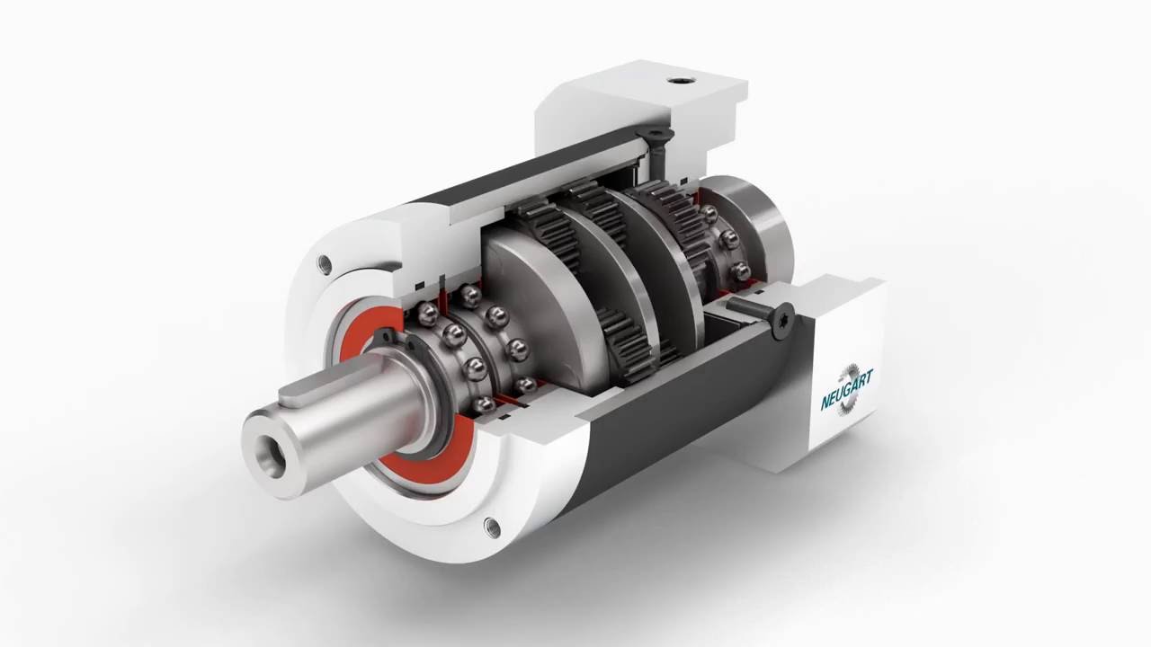 the gearbox style. A simulation-based screening and validation have already been performed which show the proposed model is usually effective and produces satisfactory shift quality through better torque features while shifting the gears. A new heuristic solution to determine suitable compounding arrangement, based on mechanism enumeration, for designing a gearbox design is proposed here.
 is a setscrew-type shaft collar for applications helping low axial loads and basic positioning. Setscrew collars possess improved holding power when the shaft material is softer compared to the setscrew material. It really is made of aluminum for level of resistance to corrosion and tarnishing and is lightweight for make use of in applications where materials weight is a concern. This collar has a forged setscrew for securing the collar onto the shaft. The operating temps for this collar range from -40 to 107 degrees C (-40 to 225 degrees F). This shaft collar is ideal for use in various applications, including in the automotive industry to situate elements in automobile power steering assemblies, the manufacturing industry to locate parts on a conveyor belt system, and the hobby craft market to hold wheels on axles in handy remote control vehicles, among others.
 all screws are pulled up and the bushing is square into the hub.
  – Matches: [ S, SC, SC-3, SC-4, SO (As a differential brake pinion shaft seal) ], [ Super 400, 1030, 1030 Comfort King, 1031, 1032, 1070, 1090, 1170, 1175, 1200TK, 1270, 1370, 1470, 1570, 2090, 2290, 2294, 2390, 2394, 2470, 2590, 2594, 2670, 3394, 3594, 400, 401, 402, 403, 405, 410, 411, 412, 413, 414, 415, 425, 4490, 4494, 4690, 500, 520, 610, 620, 700, 701, 701B, 702, 702B, 703, 703B, 705, 705B, 710, 710B, 711, 711B, 712, 712B, 713, 713B, 715, 715B, 725B, 730, 730CK, 731, 732, 733, 734, 740, 741, 742, 743, 744, 770, 800B, 801, 801B, 802, 802B, 803, 803B, 805B, 810, 810B, 811, 811B, 812, 812B, 813, 813B, 815, 815B, 830, 830 Convenience King, 831, 832, 833, 840, 841, 842, 843, 870, 900, 900B, 910, 920B, 930, 930 Ease and comfort King, 931, 932, 940, 941, 970 (all used as a front side crankshaft essential oil seal) ], [ Cruz Air: 45, 45B (all utilized as a front side crankshaft oil seal) ], [ Excavator : 40D, 40E (all used as a front crankshaft oil seal) ], Industrial: W7C (all used as a front crankshaft oil seal on rubber tired loaders); Replaces: A157044, A23433, A24715, A27838, A40349, A57342, A62049, O3866Abs, O8583AB, O9708AB, T34263
 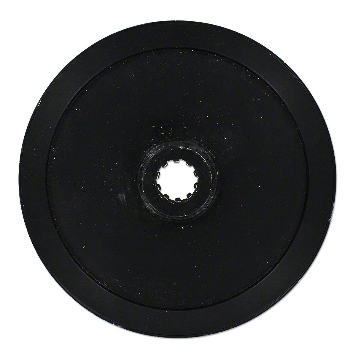 Fits: [ S, SC, SC-3, SC-4, SO (As a differential brake pinion shaft seal) ], [ Super 400, 1030, 1030 Comfort King, 1031, 1032, 1070, 1090, 1170, 1175, 1200TK, 1270, 1370, 1470, 1570, 2090, 2290, 2294, 2390, 2394, 2470, 2590, 2594, 2670, 3394, 3594, 400, 401, 402, 403, 405, 410, 411, 412, 413, 414, 415, 425, 4490, 4494, 4690, 500, 520, 610, 620, 700, 701, 701B, 702, 702B, 703, 703B, 705, 705B, 710, 710B, 711, 711B, 712, 712B, 713, 713B, 715, 715B, 725B, 730, 730CK, 731, 732, 733, 734, 740, 741, 742, 743, 744, 770, 800B, 801, 801B, 802, 802B, 803, 803B, 805B, 810, 810B, 811, 811B, 812, 812B, 813, 813B, 815, 815B, 830, 830 Comfort and ease King, 831, 832, 833, 840, 841, 842, 843, 870, 900, 900B, 910, 920B, 930, 930 Convenience King, 931, 932, 940, 941, 970 (all used as a front crankshaft oil seal) ], [ Cruz Air: 45, 45B (all used as a front side crankshaft essential oil seal) ], [ Excavator : 40D, 40E (all used as a front side crankshaft essential oil seal) ], Industrial: W7C (all utilized as a front side crankshaft oil seal on rubber exhausted loaders); Replaces: A157044, A23433, A24715, A27838, A40349, A57342, A62049, O3866Abdominal, O8583AB, O9708Abdominal, T34263
  (relative to axis of the apparatus) and take the shape of a helix. This enables one’s teeth to mesh gradually, starting as point contact and developing into line get in touch with as engagement progresses. One of the most noticeable benefits of helical gears over spur gears can be less noise, especially at moderate- to high-speeds. Also, with helical gears, multiple the teeth are often in mesh, this means much less load on each individual tooth. This outcomes in a smoother changeover of
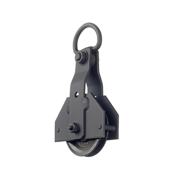 to adapt the speedometer after modifying the drivetrain.
 them to follow paths of different lengths, as when turning a corner or traversing an uneven road.
 those that the corresponding crown equipment has the teeth that are straight and oblique.
 to 6-volts and it is our best all-purpose motor. It really is ideal for tinkering with direct current (DC) electricity or creating motorized tasks of your design. It may also be utilized as a small DC generator.
 a clean, dry, stable compressed air flow. The compressed surroundings partly made up of high genuine oxygen and high purity nitrogen to supply trimming gas to the cutting head. A part supplied to the cylinder of the clamping table as a power source. And the last part can be used to blow and dirt the optical path system.
 condition.
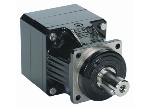 time, about 4 weeks.
 & selection assistance, please call, fax or email us. Your application facts will be reviewed by our engineers, who’ll recommend the very best solution for the application.
 stator winding, a pulsating magnetic field is produced. In the pulsating field, the rotor will not rotate because of inertia.
 an individual phase induction electric motor is wound with single phase winding. When the stator is fed with a single phase supply, it produces alternating flux (which alternates along one space axis only). Alternating flux functioning on a squirrel cage rotor cannot produce rotation, only revolving flux can.
 used in almost every market and are available in a
  types of transport elements, hydraulic components, essential oil coolers and our own monitoring program the Beegle. Do you want to know more about a product or do you have a question? Our specific sales engineers will end up being happy to assist you in finding the best product needed for you technical concern. Feel absolve to contact us in case you have concerns or seek information.
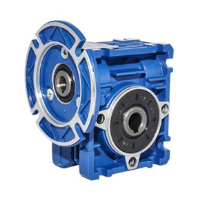 and maximum torque (expressed in newton meters, N.m) that can be supported by each of their products. The torque density varies according to the gear reducer. For example, planetary gearboxes possess a high torque density.
 full 360-degrees.
 air to fill gas cylinders, providing moderate-pressure climate to a submerged surface supplied diver, providing moderate-pressure climate for driving some
 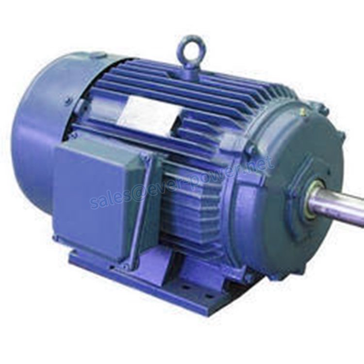 AC line current in the stator induces a current in the rotor which interacts with the field and causes the rotor to rotate
 ratios to meet up a range of application requirements.
 and chains (with varying size sprockets) to create high torque or medium torque with higher speeds!
 centering kits with grease fittings and are then completely greased with the proper lubricant. All shafts happen to be straightened and computer balanced and tested to closer tolerances than OEM requirements.
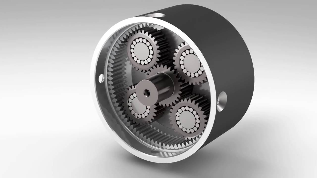 integer. The same rules apply in a substance epicyclic, but the fixed coupling of the planets gives another level of complexity, and correct planet spacing may necessitate match marking of pearly whites.
 loop mode where a command causes a simultaneous, fixed-ratio Frequency and Voltage alter.
 also o rings and seals. You have to be in a position to get the extra parts very easily as these parts should be replaced periodically if they wear out. For MAX Groupings’ winches, we generally slot in a
  the type of oil flow. This mechanical energy is usually taken from what’s called the primary mover (a turning push) like the power take-off or straight from the truck engine.
  actuator used to supply unidirectional force through a unidirectional stroke. Hydraulic cylinders are found in almost every market and are available in a
  shaft. Gear pumps are rated when it comes to the pump’s maximum pressure rating, cubic inch displacement and maximum insight speed limitation.
  shaft.
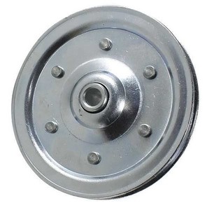 shell that does not transfer power to a shaft, but is utilized to guide the cable or exert a drive, the supporting shell is called a block, and the pulley may be called a sheave.
 poles of the magnet connect to the poles of the electromagnet, causing the motor to turn. … The more coils, the more powerful the motor.
 industrial, and home, applications, such as fans, pumps, compressors, elevators, and refrigerators. Also, they are the central parts in motor vehicles, heating ventilating and cooling (HVAC) equipment, and kitchen appliances.
 engine, capacitor and quickness control switch is still installed nevertheless the cord itself is normally detached as observed in the photos. (Discover “Control Notice” below for modify type.)
 also deliver complete gearmotors offering our industry-leading Ever-Ability Series servo motors preassem bled to a choice of Gearheads.
 I’d suggest BLDC ( because of its huge market penetration recently,ease of availability and easier electronic devices/
 tools as they are light and easy to handle
 lead times in the market on special bearings.
  air, drinking water, metals, and nutrients) into more than 70,000 different products.
 food producers battle to keep pace with the world’s expanding population.
 clean mixture of H2O.
 & physiotherapy tables
 the planetary gearbox configuration provides the highest effectiveness and best output torque of all our acceleration reducers. DC motors coupled with planetary gear reducers are well suited for apparatus in the agricultural and structure industries. With 18 ratio choices which range from 5:1 to 1000:1, we have a DC planetary gearmotor answer to fit your needs.
 the air compressor. It must ensure that the work efficiency is high and the maintenance is certainly low.
 could be confusing. For those who have any problems about employing snatch blocks, choosing wire rope blocks, functioning load restrictions, etc., contact one of our sales specialists . They are able to help you find just what you will need to get the job done safely.
 the power that can be used to light homes and power TVs in North America. Today, most commercial structures in the US use the 3 phase alternating current motors due to its flexibility an power density. The 3 phase AC engine is particularly common in large businesses which includes in the production and industrial businesses.
  the producer re-configures a stock device to fit various devices or for a particular performance. They can install a C-face
  & gas marketplace is majorly related to the fast technological advancements in the oil & gas industry.
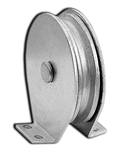 frictional forces and brake capacities of conventional V-belt pulley devices and wedgy technology. The new pulley theory allows perfect power tranny and brake capabilities with no additional brake portion or locker by moving the wire rope through the pulley. And the brand new theory allows for Ever-ability winch pulleyto work very well at any length and under any circumstance (vertical/horizontal/slant). Furthermore, Ever-electric power winch pulleyitself can approach along a fixed wire or cable.
 hardening steel, accurately generated, ground and super finished. The worm tires include phosphor bronze centrifugally cast rims of substantive sections welded to rigid centers. Considerable overall flexibility of shaft layout is permissible with all types of Double Reduction devices.
 serpentine belt under constant tension. Its design allows it to keep the serpentine belt taut, in order that the other accessory pulleys rotate at the same rpm (revolutions per minute) while under the same safe pressure. Tensioner pulleys can also absorb moderate shock loads that happen when the air conditioner cuts on and off. As a frequently rotating part, the pulley tensioner can provide off some warning signs before failure.
 final break (this
 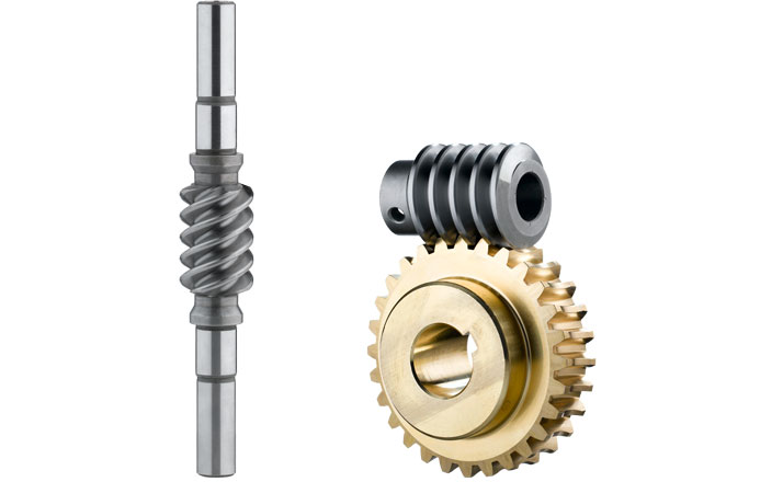 can generally be supplied (from our) warehouse in a broad collection of axial distances and gear ratios with fine levels of differentiation. We are able to also calculate and produce customer-specific axial distances and gear ratios at the plant. We prefer to produce worm gear models for right-handed users, but these models can be designed for left-handed users on demand.
 trapezoidal spindle happen to be self-locking, making them ideal for a variety of solutions.
 more vehicle manufacturers have integrated timing chains back to some vehicles with vast improvements like a reduction in noise and vibrations, different then a timing belt not absolutely all water pumps are driven by the timing chain. Check your owner’s manual to know what kind of timing operation your vehicle utilizes as they may vary from year to yr and by a car manufacturer.
 suited, as a result, in handling materials with a inclination to pack and corrode.
  comparable units to a bundle, carton, etc. going over the driven rollers. Rated speed applies to apron/slat conveyors and drag/chain/tow conveyors aswell.
 Maximum operating load limit that will be applied in immediate tension to a fresh and undamaged chain
 gripping; this tranny was also engineered for transmitting power or higher speeds than this was allowed for roll chains.
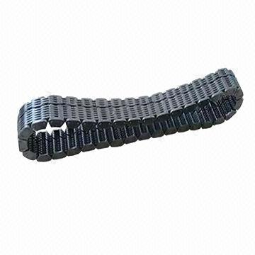 chain drive, however, build relationships the sprocket teeth with little influence or sliding, and because of this a silent chain generates less vibrations and noise than various other chains. The amount of noise generated by a silent chain drive is dependent of many factors including sprocket size, swiftness, lubrication, load, and drive support. A link belt silent chain contains removable links joined by rivets or interlocking tabs. These chains provide advantage of set up without dismantling drive parts, reducing inventory, and raising temperature ranges
 you need? Ever-power’s engineers will continue to work with you to create the required profile, just E mail us!
 for applications that want strong
  linkage is designed so the driver has to unmesh one gear before having the capacity to mesh another. With these more aged transmissions, gear clash is a issue because the gears are all rotating at unique speeds.
 and more. For more information on hollow pin roller chain or even to get a quote, please e mail us and we’ll be happy to assist you.
 but not too big to match into tight spaces
 dried mud and debris). That’s portion of the cause we put so much focus on keeping the undercarriage clean
  a sprocket has worn, it could cause rapid chain wear and will must be replaced at the first available opportunity.
 duplex.
 into existing applications, while imperial output bore dimensions allow for the application of regular U.S. imperial dimension brain shafts and important sizes. The aluminum casing is certainly fin cooled and offers a greater degree of corrosion resistance not really found in cast iron worm equipment units.
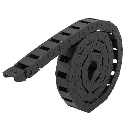 loading your configurations
 will be happy to assist you
 M2.0
M2.0 
 icultural equipment, gears, shafts, and so forth.
 curves with middle line radii no more than 18 in .. Its wide-web best design provides a lot more than enough carrying surface. Available in HZPT File-Hard Promal(Duramal) , MC-33 Chain is normally interchangeable with
  single pendant. Conventional steel or multi-flex plastic chains are commonly found in linking the gears. Consequently, this course of conveyors is best suited for make use of in transporting items with high load capacity.
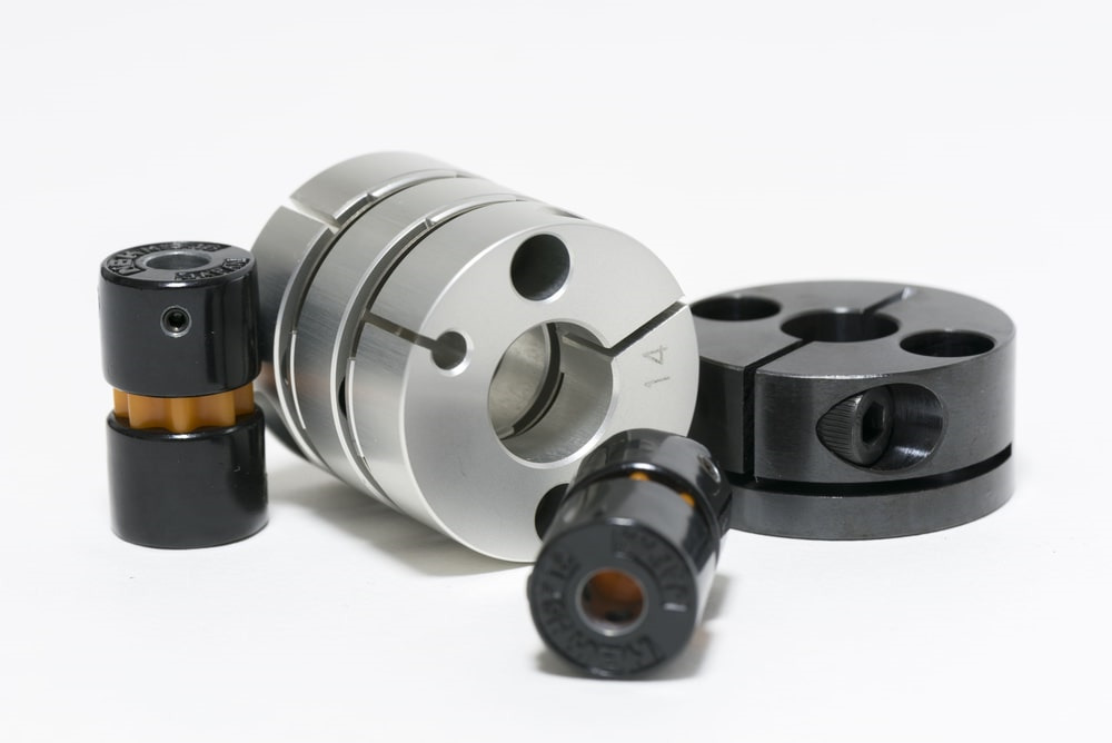 element is made from nylon or another plastic material to eliminate the lubrication requirements. You will find a reduction in torque potential in these unlubricated varieties compared to the more conventional designs.
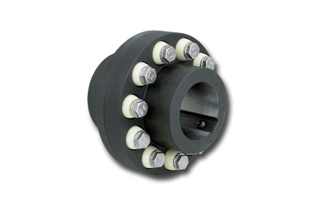 atmospheres; certified acc. to 94/9/EC (ATEX 95)
 the monitor chain works together with the conveyor to make a complete system
 words, they are involute gears employing part of the involute curve because their tooth forms. Looking generally, the involute shape is considered the most wide-spread gear tooth contact form due to, among other reasons, to be able to absorb small center distance errors, easily made development tools simplify manufacturing, solid roots of the teeth make it strong, etc . Enamel shape is often described as a specification in drawing of a
  like the roller chain. However, it does not possess friction – reducing rollers and can be thus suitable rather for lower generating speeds. The permitted standard
  bronze, ASTM B-147, Alloy 8A.
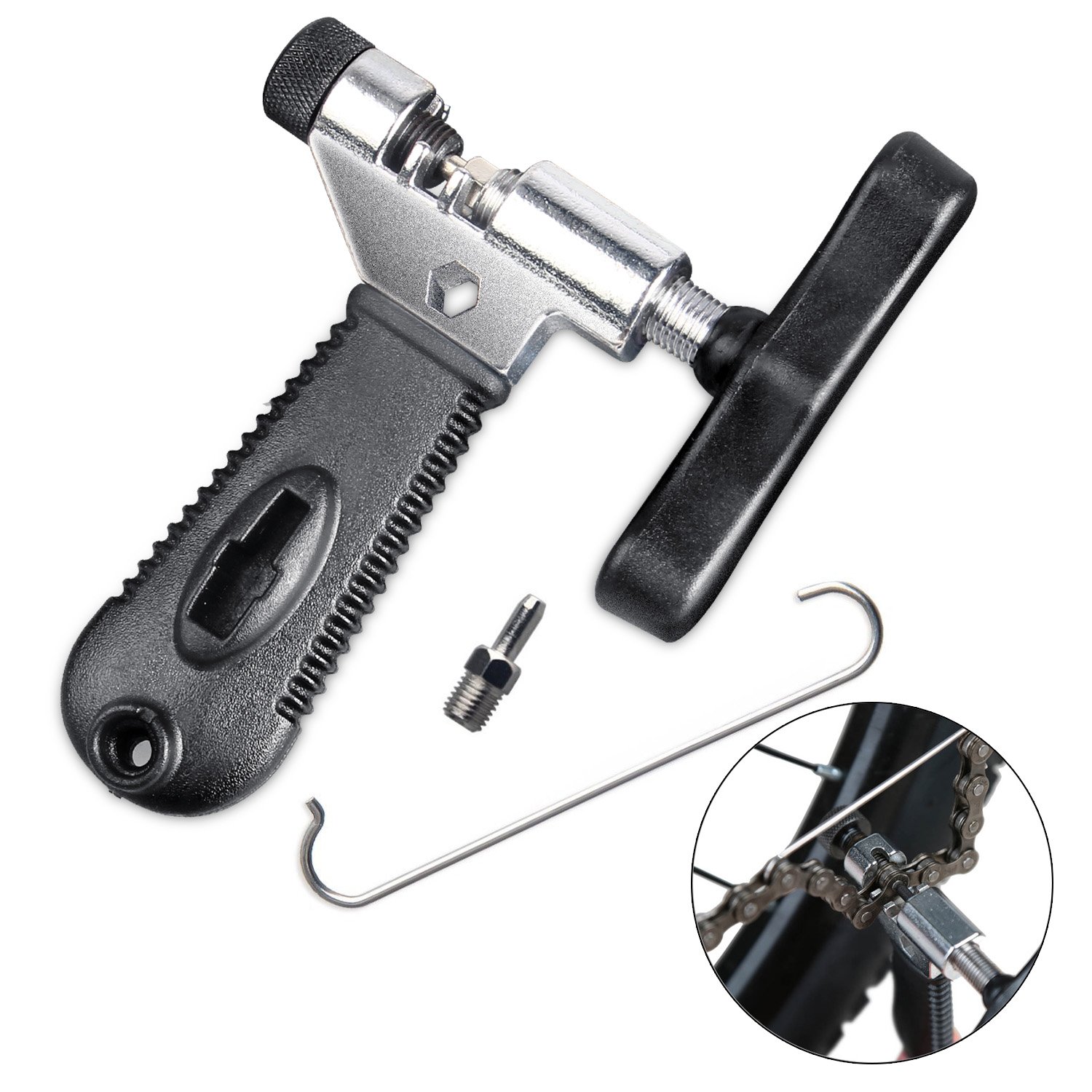 chain back again together, line everything up and push link pin back in
 Quadruplex
 used for nonintersecting but perpendicular shafts. Two mating crossed helical gears (also known as screw gears) must have same module, same pressure position and either same or opposite hand of helix. This type of gear has software similar to worm gear; however, worm equipment is favored for steep speed reduction (1:15 to at least one 1:100), whereas crossed helical gears cannot offer quickness reduction beyond 1:2. Various differences between parallel helical gear and crossed helical gear are given below in desk format.
 limited software. Rigid couplings do not have the capability to compensate for shaft misalignments and are as a result used where shafts are already positioned in exact lateral and angular alignment. Any misalignment between shafts will create high stresses and support bearing loads.
  on the worm equipment. But worm gears have sliding contact which is calm but will produce heat and also have relatively low transmission efficiency.
 expertise to manufacture
  don’t have for offsets and a significantly reduced threat of overheating. Curved tooth and deeper traction between those teeth ensures greater asset availability to boost flexible performance and lengthen equipment life.
 reported to be self-locking. This assumes a statically loaded program with little or no vibration as this might cause the friction position to be conquer and the combination to untighten. In systems that are at the mercy of vibration a locking mechanism or brake is preferred to prevent back-drive.
 pair’s same quantity of teeth. Their purpose is limited to the transformation in transmission direction. Because they are a type of bevel gears, the basic
 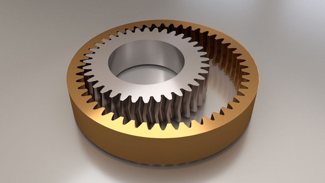 adopting equipment that may cut them by simply making pinion cutters and not needing helical guides.
 to AGMA and equivalent quality levels. We make metric gears for the next industries: aviation, defense and aerospace instrumentation, industrial, energy, general market and equipment, healthcare, leisure, musical instrument, power tool, scientific analysis and transportation.
 velocity, there is no relative motion between your differential side gears and pinions, and they all rotate as a device with the case and ring gear. If the automobile turns to the left, the right-hand wheel will be forced to rotate faster than the left-hand steering wheel, and the medial side gears and the pinions will rotate in accordance with one another. The ring equipment rotates at a swiftness that is equal to the mean speed of the left and right wheels. If the wheels are jacked up with the transmitting in neutral and among the wheels is turned, the contrary wheel will turn in the opposite direction at the same quickness.
 in the Series H coupling, sizes 8 to 30. This tooth type distributes contact pressures over the full amount of the hub tooth, to greatest develop the required lubricating film, minimizing tooth use and extending coupling support life for years of operation. THE FINISH Rings are detachable for ease of assembly and to enable inspection of the gear sets.
  or sprockets onto shafts.
 the drive or roll-up tubes attached to ends.
 and surface worms are designed for remarkably
  support is fantastic” Customer – Bill Power System
 one stage; size dependent, Sector gears
 to 210 mm, module from 0.5 to 10, shaft duration up to 500 mm
 Tool steel
 torque may need to be delivered to each wheel. Worm gears are used to provide the required torque that governs each wheel’s performance.
 Type. Right Type couplings are composed of coupling halves that are split perpendicular to the shaft axis. A hardened steel silent chain joins both halves. Diagonal Type couplings are split at an angle to the shaft axis. Due to the angular split, the chain that wraps a Diagonal couplings is normally loaded in shear,in addition to tension. This outcomes in Diagonal couplings having a somewhat higher load capability than right couplings, where in fact the chain is only loaded in shear.
 is performed by we of quality controllers for delivering only error-free products on the market. Apart from this, our streamlined process control, dedicated associates and keeping quality in the products has helped our company to attain maximum growth in the industry.
 rotates, it throws liquid in to the pump and forms a liquid band concentric with the pump shell. The liquid ring and the rotor blade type a rotating
  can reach a pressure of just one 1 x 10⁻⁴ Torr. Rotary piston pumps could be prepared for corrosive and oxygen assistance.
 rotors and the end cover, so the pump efficiency is stable and long service time. low maintenance cost
 getting used for light commercial works, medical industry, printing and instrument industry, plastic, food and packaging, electronic,
  living area needed
 that flows through special pockets in the component casing.
 of oil is essential to keep it functioning as it should.
 velocity characteristics and structural mechanism.
 with not involute form for reduced noise
 milking
  ready to deliver it to you immediately. If you’re not sure which type of air compressor is the right fit for your market or business, just get in touch with us, and we’ll help you number it out. We are able to help you determine all of your air compression system needs.
 recharge. Before recharging you wish to make sure the machine is free from any unwanted gasses, air, or water. If these were to stay in the machine, it could turn the oil it operates on into sludge and keep behind
  to conventional Roots pumps. This is due to a get with energy efficiency course IE4 and the unique rotor geometries of the pumps. The pumps are hermetically sealed to the atmosphere and also have a maximum essential leakage rate of 1·10-6 Pa m3/s. Dynamic seals are eliminated and, consequently, maintenance is only needed every four years. An innovative sealing concept in the suction chamber makes the use of sealing gas superfluous generally in most applications, which also offers a
  over factory certified
 of period and will affect the filtration effectiveness without the need to replace or clean the oil-water separator
 the hub, should it already be installed.
 is for reference only. Severe problems could call for bigger hub and in some situations a marginally scaled-down hub may possibly be satisfactory. Inquire about spe
 cific software.
 compressor area and environment.
 operate at other
 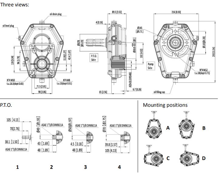 a few L/Min 190 Bar
 L/Min 95 Bar
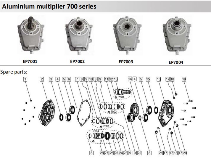 your technique. Normally forged in mechanically-resistant iron or housed in shell-cast aluminium, our models are designed for connecting equipment pumps to electrical power get off techniques.
 tilting
  worm gears and worm shafts in metal, stainless steel, aluminium, bronze and cast iron according to task requirements. Our company can be an ISO 9001 qualified one-stop service center that meets all your requires for worm gears and worm shafts. As the leading producer of worm gears in China, HZPT welcomes your regular orders and custom orders. Please send out us your request.
 without disassembling them; furthermore the versions with swinging apart covers allow the lateral flanges to end up being installed on both sides with simple fixing
  vacuum, of 0.010 Torr (10 microns, 1 x 10⁻² Torr or 0.0133 mbar).
 high-pressure hydraulic pumps and in automobiles, including supercharging, power-steering, air conditioning and automatic-transmission pumps. Pumps for mid-range pressures include applications such as for example carbonators for fountain soft-drink dispensers and espresso coffee machines.
 that define a dried out vacuum pump.
 chamber. No lubrication means the dry vacuum pump operates without drinking water, oil or any various other liquid. This outcomes in major advantages like no process contamination and no pollution caused by the pump operation.
  to standard screw styles. It also results in a lower heat load of the compressed gas.
 switch in torque. If one equipment is larger than the other, a mechanical benefit is created; the rotational acceleration and torque of the respective gears differs compared to their diameters.
 aids in preventing contamination of the pumped gas by ambient atmosphere. Maintenance is limited to changing the scroll tip seals which may be easily carried out by the operator and with no need for special tools.
 lubricant increases efficiency; with 2,000 hours of service between changeouts, it performs four instances longer than petroleum-centered lubricant Two-Year Warranty Available: Buy an All-Season Select lubricant start-up package, and receive all the parts you need for start-up and the initial year of maintenance, along with an extended pump warranty
 allowed us even to be present in different sectors such as home automation, and devices for vehicles or systems related to physical disabled.
 combination of the reciprocating actions of a rubber, thermoplastic or teflon diaphragm and suitable valves on either side of the diaphragm
 above is called a worm and worm wheel. The worm, which in this example is certainly brown in colour, only has one tooth nonetheless it is like a screw thread. The worm wheel, coloured yellowish, is like a normal equipment wheel or spur gear. The worm always drives the worm wheel round, it is never the opposite way circular as the
  machine is designed to ensure that the worm can easily turn the gear, however the gear cannot turn the worm. In some designs, the friction between your equipment and worm retains the worm in place. This feature can be extremely useful in a few applications.
 from corrosion. The pumps achieve their distinctively powerful from high pumping chamber quantity in accordance with the minimal lifeless space. Highly flexible dual diaphragms with fabric reinforcement make certain an exceptionally long diaphragm lifetime. The pumps operate definitely oil free and do not have any sliding parts in the gas path. In normal procedure they are free of abrasion. Besides adding to the long assistance intervals the lack of abrasion also eliminates most of the particulate impurities frequently generated within scroll or piston pumps. This makes diaphragm pumps a good choice for clean applications.
 is a perfect match for most applications in the laboratory and operations since it is oil-totally free and whisper quiet, and because it requires so small service. Diaphragms have especially lengthy lives and hermetically seal the drive space from the pumping chamber to safeguard mechanical parts from corrosion. The pumps accomplish their
  pump works with a sealant required in its procedure. This liquid can be water, essential oil or any other solvent which is certainly rotated by an impeller within the casing of the pump.
 can be found in 303 stainless for use with one, double or 4 thread wheels.
 types of pumps and centrifugal is that positive displacement pumps will move fluid at the same acceleration regardless of the strain on the inlet end and centrifugal pumps will not
 interface is formed to open slightly positive pressure), stretching (compressed exhaust slot is closed, a negative
  properly used, worms and worm gears supply the smoothest, quietest kind of gearing.
 the generator, creating suction and vacuum. The surroundings stream exits through the exhaust. … These operations require vacuum pumps.
 and by adjusting the amount of threads, different ratios may be accomplished without altering mounting arrangements. A unique feature of Worm and Wheel assemblies is definitely their capability to prohibit back driving
 substance or physical-chemical ways of pump air away of a container to get a vacuum.Generally speaking, vacuum pump is a device that improves, generates and maintains vacuum in a closed space by just various means.
 used to seal the piston to the cylinder.
 the lubrication problem by coating the compression element with a pre-lubricating materials like Teflon. Some oil-free compressors may also use water in place of oil for the lubricating and cooling process. These alternate materials guard the pump and allow the mechanism to move smoothly without the need for any oil-centered or synthetic lubrication.
 alloy steel and are the hardened for optimum chain life.
 provides planetary pushed units for extreme and heavy-obligation apps. You should evaluation our full line of hydraulic auger methods to see which Danuser device greatest suits your requirements.
 An outstanding cost with large-obligation functionality. Units range from 6 – 35 GPM and up to 3000 PSI. Mounting is available for entrance-conclude loader, skid-steer, excavator, mini-excavator, and backhoe.
 ies.html]#CLP/CC 150 (ISO 150) (SAE ninety). The oil degree have to be constantly checked via the specific degree gauge. Oil has to be transformed between the very first 30 to 50 hours of use and subsequent adjustments at minimum every single 12 months.
 x.xyz/Content/upload/2018369030/201811071613151457956.jpg]#90° ANGLE GEARBOX / Solid IRON / FOR AGRICULTURAL Equipment
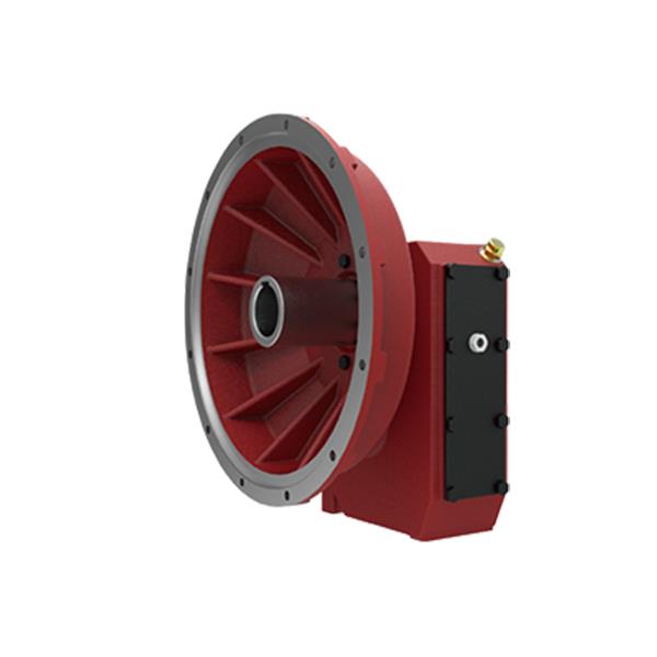 right angle shaft pace increasers and reducers), driveshafts and safety products largely used on agricultural equipments.
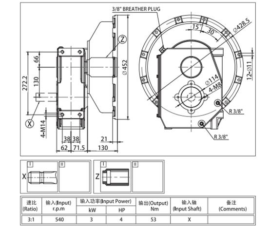 engineering and large layout capacity let to fix any customerâs issues, granting constant enhancement, quality and overall provider.
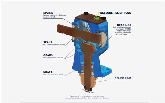
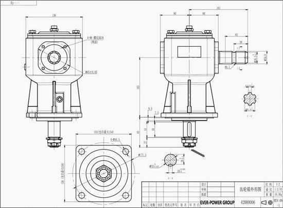 established-up and calls for significantly less maintenance than a seven-hundred sequence or related multi-gear transmission. By decreasing the quantity of relocating elements and trying to keep issues easy this gearbox is the go to for any construct in which principles allow.
 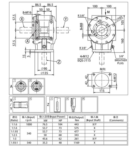 DO YOUR Merchandise RELATE…
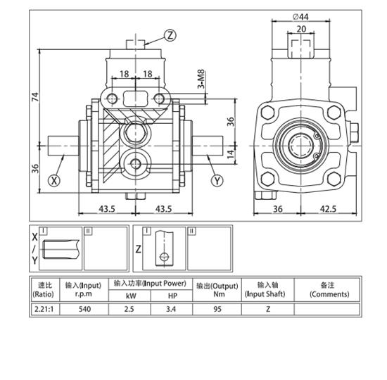 want.
want.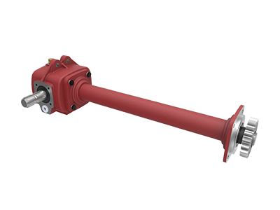 consumers from virtually 30 nations around the world in so numerous a long time.
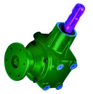 control the direction of the material that is thrown from the spreader. All broadcast spreaders need some type of electricity to spin the disk. On tow behind models, the turning wheels are the floor generate for the gear box to s
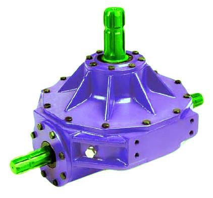 pin the disk. A tractor, 3 level hitch mounted device is PTO pushed.
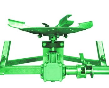 Rotary Mower Components & Gearboxes
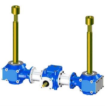 any difficult job you need to tackle. Search our assortment to learn your many options in these essential parts to keep daily life on the farm managing